I have a drawing (see the 2 images) that I need help interpreting.
Today I have a ceiling with plasterboards nailed onto some sort of cladding (right word?) with cc300.
I was thinking of lowering the ceiling and thought it would be best to find the rafters for support so that my new ceiling doesn't risk falling down.
The ceiling is a low-sloping "flat roof."
But I don't quite understand how the "section rafter" looks in reality.
As I interpret it:
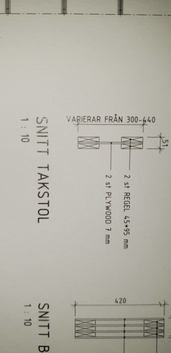
If I look straight up at my ceiling, I should see 2 battens with a plywood board between them "closest to my head" right behind the plasterboard.
The plywood board then goes straight up to the next pair of battens, and one might say that it functions as a divider between each rafter?
Looking at the picture labeled "section rafter," it says 2 pcs 45x95mm + 2 pcs 7mm. But a total of 51?
Next to this is "section beam A," which I unfortunately didn't get in the picture, I realize now.
It specifies 3x22mm + 4 pcs 7mm and a total of 94, which matches, so I suspect there's a mistake in the "section rafter."
In short, am I "correct" in assuming that when I look "straight up," there should reasonably be 2 battens that I can attach my new ceiling to?
Perhaps unnecessary info in short:
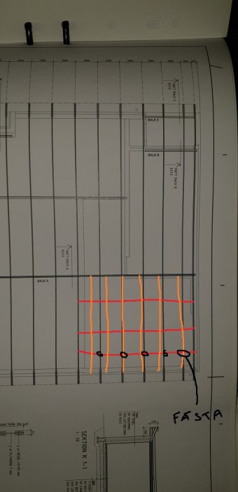
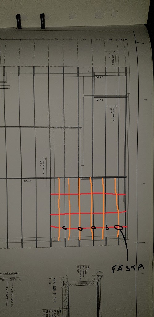
I will attach 3 pcs 45x145 in the rafters (longitudinally) and then attach 11 pcs 45x45 battens "crosswise."
Insulation will be added in all corners, and there won’t be much weight except for some MDF in a few well-selected spots. The rest will be fabric covering the ceiling.
Maybe I should just skip the wide battens and attach the 45x45 battens to the walls, and then have the attachment point in the ceiling with metal bands or whatever they're called.
Any tips?
The trusses are a form of I-beams where the web height varies between 300 and 440 mm to create some slope on the roof. What is called a beam is a similar, slightly heavier construction that probably exists as a transverse main beam somewhere. The trusses and the beam are mounted upright; otherwise, they don't have much load-bearing capacity.
It is fine to attach wood to the underside of the trusses. However, I am a bit doubtful about your sub-roof construction. 45x45 lumber cannot have very large distances between fastening points, even if they are only lightly loaded. In general, it is not suitable to use lumber with a square cross-section in horizontal frames. You make better use of the material if it is narrower and taller. Create a dimensioned schematic of how you envision the sub-roof, and you can get more concrete help.
However, I am a bit doubtful about your ceiling construction. 45x45 timber cannot have particularly large distances between fastening points even if they are only lightly loaded. In general, it is not suitable to use timber with a square cross-section in horizontal load-bearing structures. You utilize the material better if it is narrower and higher. Make a dimensioned sketch of how you envision the ceiling so you can get more concrete help.
Thanks for the response!
I made a rough sketch. The reason for the 45x45 beams is precisely because the only weight I will hang is 3 strips of MDF (approximately 20x200x5900mm) and 1 MDF board that will have a box for my projector. At the wall/ceiling edges, there will be insulation (190x400x5900, i.e., along the wall). It should preferably be as open as possible since, depending on the room's acoustics (home theater), I want to be able to install diffusers or more damping. Everything will be hidden by fabric. That is, it is very lightweight items that will be hung (mounted) on the load-bearing structure. If anything more is needed, I'll attach it to the rafters with more fastening points.
Edit: I plan to have 3 load-bearing beams (45x145) and 11 secondary (45x45) studs so that there will be a CC of 60cm.
I'm definitely not a professional, so all input is welcome!
What is interesting is both the distance between the attachment points for your 45x45 reglar and how they are loaded and where. It doesn't take much for the 45x45 reglar to start sagging between the attachment points.
What is interesting is both the distance between the attachment points for your 45x45 beams and how they are loaded and where. It doesn't take much for the 45x45 beams to start sagging between the attachment points.
I understand.
Since the roof beams go every 1.2m, the attachment points for 45x145 will be along the long wall. Then it will be divided by the width of the room.
Today, there is some form of plank (sparse panel?) with cc300 transverse roof joists that the gypsum is attached to. I could attach my 45x45 beams to these using mounting straps or some angle brackets for "offset," if that is the correct term. I thought that the 45x45 beams would act as stiffer than, for example, 28x70 sparse panel.
But then maybe I should reduce the CC distance of the 45 beams to 450. Then it should be quite durable and not flex at all if I decide to add more MDF or gypsum in the future.
It's not the c/c distance between the 45x45 studs that is interesting, but rather the distance between their fastening points. A 28x70 set on edge and containing the same amount of material as a 45x45 is significantly stiffer against deflection. For a 45x45 that also takes up a small load, 1.2 meters between the fastening points is too long. Over time, it can become noticeably wavy, especially if it is of poor wood quality (which most 45x45 are).
It is not the c/c distance between the 45x45 studs that is interesting but rather the distance between their anchor points. A 28x70 that is set on edge and contains as much material as 45x45 is significantly stiffer against deflection. For 45x45 that also takes even a small load, 1.2 meters between the anchor points is too long. Over time it can become noticeably wavy, especially if it is of poor wood quality (which most 45x45 are).
Do you have any suggestions on what I should do?
I would preferably like wood studs.
Perhaps replace my primary studs with 45x120 and then the secondary with 45x70. Both standing on edge. And perhaps add an additional primary stud as more anchor points.