I am working on a design that will require glulam beams with a decent span, but my question is how to construct the "corners"?
It will be insulated, so it would be quite appreciated if it is reasonably even on both the inside and outside and if there aren't too many thermal bridges.
So it's not about sizing, a constructor will look at that, but how to cross and intersect studs/beams/posts, etc.
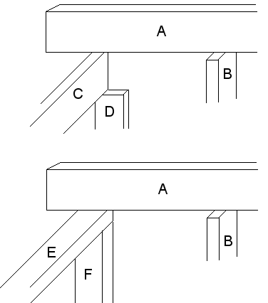
The glulam beam (A) is one of five pieces.
The stud (B) is vertical and the intention is to insulate on that side.
In the upper variant with a vertical stud (C), the part between C and D becomes awkward, and how do you insulate between B and D?
In the lower variant, it looks nicer between E and F, but I'm quite convinced that a vertical (C) of decent dimension is needed to support the glulam beams. The glulam beams will be CC 120 and the distance between the vertical studs supporting C and E will be about a meter (there will be windows there, so they cannot be placed closer together).
I would be very grateful if someone could explain to me a bit about how to build... The constructor will certainly tell me exactly, but I would like to be well-prepared.
Thanks in advance
It will be insulated, so it would be quite appreciated if it is reasonably even on both the inside and outside and if there aren't too many thermal bridges.
So it's not about sizing, a constructor will look at that, but how to cross and intersect studs/beams/posts, etc.
The glulam beam (A) is one of five pieces.
The stud (B) is vertical and the intention is to insulate on that side.
In the upper variant with a vertical stud (C), the part between C and D becomes awkward, and how do you insulate between B and D?
In the lower variant, it looks nicer between E and F, but I'm quite convinced that a vertical (C) of decent dimension is needed to support the glulam beams. The glulam beams will be CC 120 and the distance between the vertical studs supporting C and E will be about a meter (there will be windows there, so they cannot be placed closer together).
I would be very grateful if someone could explain to me a bit about how to build... The constructor will certainly tell me exactly, but I would like to be well-prepared.
Thanks in advance
Now I'm a car mechanic and prefer "carpentry" in steel, so don't put too much weight on what I say. But: In the upper example, if you let D go all the way up to A and notch out for C, it makes a bit more sense. The lower example would work if you can set F at c/c60 and brace for the windows. Then you'll have a beam under each joist. The most stable variant is a combination, with C recessed into D and an E on top. Then you can probably manage without a beam under each joist. It also feels like you need a wall plate (like E) on the B-wall as well.
Thanks! Those were great ideas, I am an IT consultant, so I'm definitely going to listen a lot to a car mechanic ")
Surely one should have a hammarband under B as well, I hadn't thought about that. I'll try to meet the constructor next week, so there will be a bit more substance. If anyone else has tips, they are gladly received.
Surely one should have a hammarband under B as well, I hadn't thought about that. I'll try to meet the constructor next week, so there will be a bit more substance. If anyone else has tips, they are gladly received.
A should lie down on the platen if you have cc60 on B. A and E can be connected to each other at the corners. Then you insulate on the outside corner, or you let D go all the way out even with B on the outside, which I believe is most common.
Was this understandable? There are many drawings online on how to build exterior walls.
/CC
Was this understandable? There are many drawings online on how to build exterior walls.
/CC
Hi!
Check here to see how to make a corner.
http://www.swedisol.se/sw1010.asp
What you should keep in mind when making the corner is that the outer wall should have something to attach to and that the inner wall also has it. Now I do think that what is described here doesn’t provide a sufficiently stable corner, and there’s a risk the corner might gap. But you can solve this by placing a metal angle bracket behind the board material in the corner and screwing straight through the board material/metal bracket into the wooden stud. Now I am primarily thinking about the one marked F3, for the other F2, you should probably do it a little differently as well.
Another thing to consider is that you can easily end up with multiple studs that draw cold into the corner.
And of course, a top plate over everything described earlier in the thread.
Last edited:
Thanks for the good link and great tips. I want to point out that A is not a hammarband but a glulam beam (rafter). But then you should have a hammarband underneath it. I do believe in the variation someone wrote "C recessed in D with an E over".
Indeed, a C is needed where there are windows... otherwise, you'd place wall studs where the beam comes. But E is probably a top plate and it should be on both walls. If you have large windows and there are multiple beams resting on a C without the force being transferred by wall studs, then C needs to be a bit extra stable (must be dimensioned correctly).
Then it depends a bit on how the beam will look if you do not also place a C on top of the top plate. But if there are solar panels, they often protrude, and then it might be smart to place a C underneath... But remember... everywhere you replace insulation with wood, you get poorer insulation.
Then it depends a bit on how the beam will look if you do not also place a C on top of the top plate. But if there are solar panels, they often protrude, and then it might be smart to place a C underneath... But remember... everywhere you replace insulation with wood, you get poorer insulation.
Click here to reply