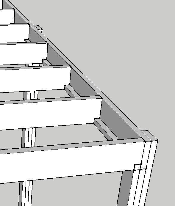
The horizontal 45 at the bottom of the support beam as a backing slat and a 45x45 notch in the floor joists I've used in a couple of other projects. If you manage to get the 45 exactly along the entire length (harder than I thought) and cut the 45x45 notch very precisely with a jigsaw (maybe better with a handsaw), you won't need to plane if you want it completely even.
The motivation has been more about saving money in those cases, as sturdy joist hangers cost about 25 SEK and if you need 20 of them... Moreover, it's tricky to place a joist hanger at the very end of a support beam (it will crack because of the screws). And a 45x45 beam doesn't cost much.
The picture someone attached of such a white-painted construction (which was very nice) makes me lean towards using that approach for both the front and rear support beams. I'm ignoring the overhang.
It's a bit tricky with the posts, I made 3 pieces of 45x120 (=135x120mm) in the CAD, but maybe the support beam should be placed directly on a 90x90 instead. Is there any smart solution?
It will be more than good as you have drawn it now, and you don't need to cut out the 45x45 notch at the places where you can let the beams rest directly, i.e., at the posts. It will be both easier to do and more aesthetically pleasing at the outer edges and better from a structural standpoint.
And in what was previously discussed, you are now back where it isn't protected against the splitting of the beams. If you choose them one module shorter in height than the carrying beams, it's much better instead.
It will be more than fine as you've drawn it now, and you don't need to remove the 45x45 notch at places where you can let the beams rest directly, i.e., at the posts. This makes it both easier to construct, more aesthetically pleasing at the edges, and better in terms of strength.
And regarding what was previously mentioned, you are now back to a point where it's not protected against the splitting of beams. If you choose them to be one module less in height than the load-bearing beams, that's much better instead.
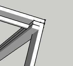
True, 45x45 isn't needed at the posts. I'll move things around a bit to see if I can keep the load-bearing beam "clean" on the outside where the gutter will be, i.e., move in the posts 45mm.
Something like that it will probably be. Feels like it will look nicer outward (towards the gutter), on the other hand, it requires a bit more handiwork with a handsaw and chisel.
Something like that will probably be it. Feels like it will be nicer outward (towards the gutter), on the other hand, it requires a bit more manual work with a handsaw and chisel.
Ok, the front support beam feels good now, so let's switch ends... Support beam on the house. The patio roof will extend along the entire house, so it's many meters.
The house is additionally insulated with west coast board/climate board, so the wall consists of:
- vertical planks.
- climate board.
- nail battens on plastic spacers (pressed through the insulation).
- vertical paneling.
- cover strips.
A support beam directly on the facade is not an option as the plastic spacers would be compressed.
So I came up with three half-decent solutions: 1. Posts on plinths against the house wall that the inner support beam rests on. It gets a little messy as there is drainage and storm water along the house wall. I'm afraid I'll place a plinth that presses on something. But for the sake of the roof, it feels quite appealing.
2. Cut up the entire panel with a circular saw (along the entire side of the house), remove insulation, inset a "bundle" of support beams that are attached to the plank wall. It will be difficult to seal and generally cumbersome.
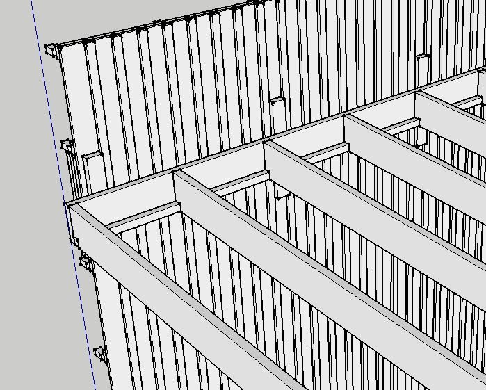
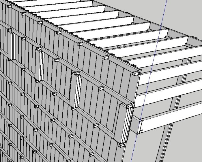
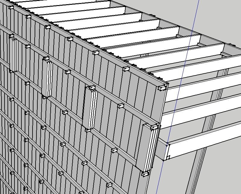
3. Remove one panel board every meter and insert a piece of timber, replace the panel board, and screw the support beam onto a spacer (as shown in the picture). There will be bending load and tension in the screws, and I'm not sure if other problems can arise with the support beam "hanging" in the air only at a few points/screws.
Imagine that insulation fills all voids here behind the panel.
With proposal 1, you have to consider how to secure it so that the entire roof structure doesn't leave the house wall and collapse into the yard when there are several tons of snow on it while a storm is blowing.
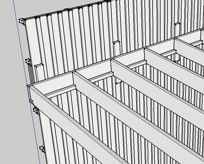
I must express a differing opinion from almost all the posts at the beginning of this thread. The bearer seems to be loaded exclusively in bending with "free" supports on the posts. The moment is counteracted by opposing stresses in the wood cross-section, where tensile stresses will be below the neutral axis and compressive stresses above. If you now carve the bearer down to the neutral layer (half the height), it is only important that the carved sides can support well against the rafters placed in the carvings. In this case, there is no significant weakening of the cross-section. However, I would avoid cantilevering the bearers outside the posts with carvings precisely above the post. This will not work.
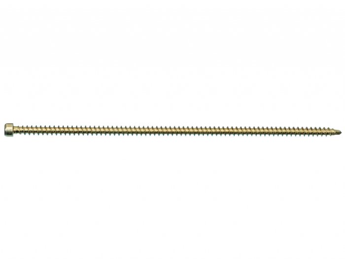
To avoid splitting at the carvings, I would place 2 Würth Assy Plus VG (6x160) with a cylinder head on each side of the carving. These can be screwed from above so the heads are not visible. I would also use construction-graded timber for this type of structure (C24).
The rafters are carved at the bottom. This also suits well for the cantilevered part. This part can be seen as a "corbel" with maximum moment near the bearer. Here, the stresses are inversely distributed; tensile stresses above and compressive stresses below. So, it also suits here with how the carving is done. Here too, I would place 2 Assy Plus VG (6x120) with cylinder head inside the carving on the rafters to avoid splitting at the carving.
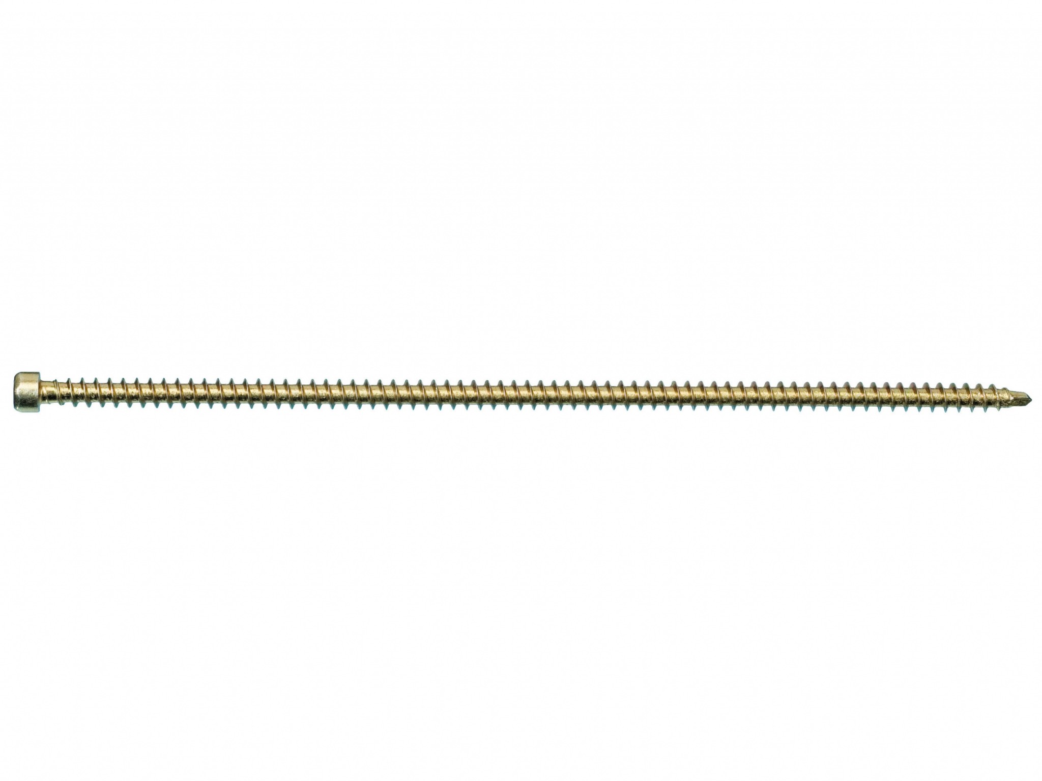
Such a screw, what is the advantage of not having an unthreaded part at the innermost section? Does it act as reinforcement in constructions where one believes tensile strength in a specific direction must be increased? For example, in this case, where there is a risk of "splitting".
It may not be suitable for joining two parts (unless predrilled) and only for solid, single pieces?
There's really no clamping length to speak of, although that might not be as important in wood...
I assume the head is mainly for screwing in and has no function at all as a load bearer.
Moreover, a cool screw that seems to be available in lengths up to 300mm.
Hi
How did you end up solving it?
I have a similar problem where I posted a thread some time ago https://www.byggahus.se/forum/byggmaterial-byggteknik/272300-dimensionera-altantak-oppen-kansla.html but in my case, I am looking for minimal construction height because I don't want to lose ceiling height floor-support beam at the outer edge. I don't know what you think about this compromise of techniques as mentioned above to keep the overhang (200 mm in my case):
If I can notch my roof beams which are 45x195 significantly at the bottom (say 95 mm) and leave the outer support beam unnotched. And at the same time I place the beams on 45x45 on both the inside and outside of the support beam as you described above.
Then I'll have 100 mm left in the roof beam to handle the tensile load from the roof overhang. Any sagging/compression in the overhang is absorbed at the bottom by the 45x45.
This way, I gain 1 dm in construction height.
Opinions?
Last edited:
Vi vill skicka notiser för ämnen du bevakar och händelser som berör dig.