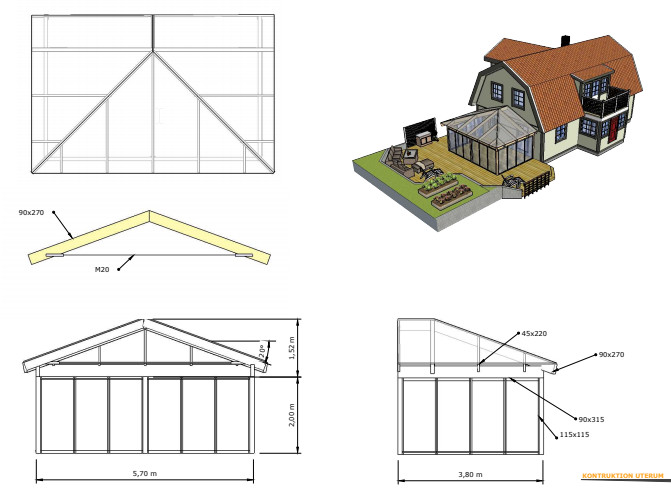
I am sketching our construction of a conservatory where we would like to have a hipped roof as we think it best matches the style of the house. The problem I encounter is that the roof, in my case, is intended to be 3.7x5.7, so there will not be a 45-degree angle on the "rafter/joist," but about 50 degrees.
And when you don't place the breaking point at 45 degrees, you get different roof angles and different eave measurements. If it had been the other way around, more than twice as wide as deep, you would solve it with a "flat" piece in the middle against the house. But does anyone have a suggestion for an elegant solution in this case?
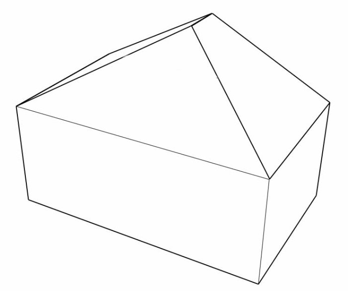
When you want a hipped roof and the shape of the building is not a square, but you want the same roof pitch on all sides, you can do as shown in this picture.
Construction-wise, it is solved with a short ridge beam whose length is 3.7 m - 5.7/2 m, i.e., 0.85 m. This ridge beam is attached at one end to the house facade. At the other end, it rests on a small column (whose height equals the roof's height), which in turn stands on a beam running across the entire room.
Surely one should be able to replace the transverse beam with a truss at the end of the ridge beam? Thinking of what might be called a three-hinged truss or tension band truss parallel to the long side. There will already be beams there to support the roof, so if you supplement with a tie rod, it should work. The truss will bear almost half of the roof's weight, but it shouldn't require very thick lumber since the largest load will be a point load at the top.
Absolutely! A distinctly creative solution, possibly a bit more expensive. You need to calculate the point load. Some diagonals are also needed in the roof plane to stabilize. It can look nicer than beam plus column plus beam.
I might need to make a complete sketch of it so that it can be calculated.
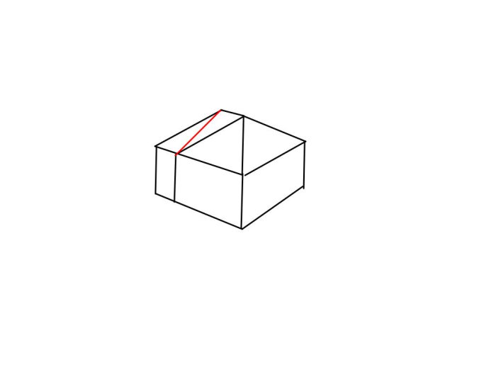
I am envisioning that the roof truss is placed at the red part (when viewing the roof from above).
Are you thinking that a diagonal is necessary between the "roof truss" and the house wall (at the top of the image)? Because the other shearing should be handled by the "corner beams" or am I thinking incorrectly.
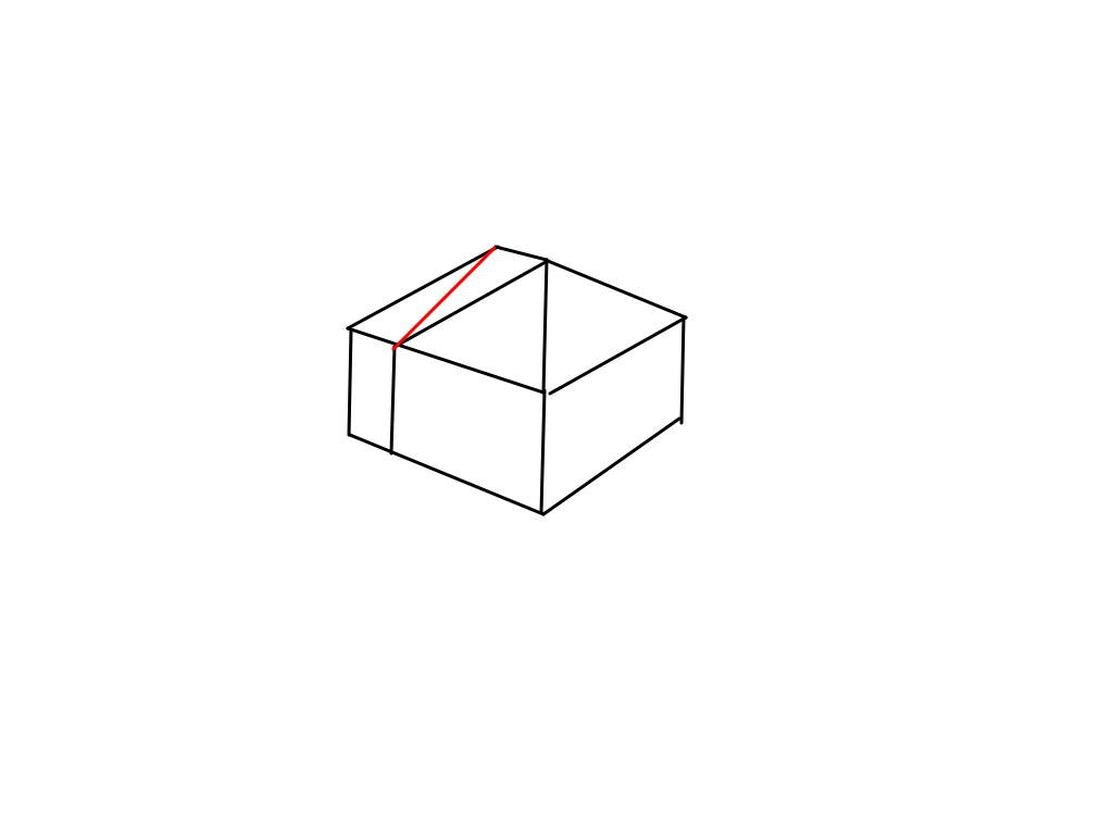
Your image is not displaying correctly. There is only a question mark. Since it's a pole building, the walls do not have a stabilizing function. You must ensure that all the posts in the structure are locked at their upper end in the horizontal plane. I have drawn a suitable diagonal in red on the image below. The point load on your roof truss top will be considerable.