Here comes another thread about load-bearing walls or not. I hope Justus, who wrote the great article, has time to respond because even though I'm educated in construction, I work in another field and haven't done construction calculations since school 15 years ago, so I want to make sure I'm not thinking incorrectly. Let me know if any information is missing (I have also described my thinking, but almost all the measurements are in the pictures).
The question in short is whether I need to add a beam or not? If so, is it enough for just one of the openings? Can I, without compromising the attic, sister between and take it down with two pillars, etc.? I simply need some sounding board help because I'm rusty.
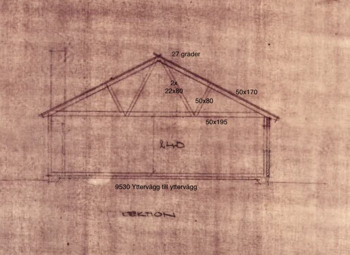
As the section of the house shows, the roof trusses are W-type trusses, which, according to the wood guide, are self-supporting in snow zone 2 up to 11 meters (the dimensions are written in the picture). In my case, it's 9.53 meters, and the lower chord is generously over-dimensioned.
All interior walls consist of 40x38mm studs with 13mm chipboard on each side, something that in my world cannot have a load-bearing effect but a stabilizing effect. Some type of KEX elements from the 60s, the studs do not connect to the underside of the tongue and groove roof but rather the chipboard does. However, the attic was originally an attic floor with storage. Today, it's furnished (light floor joists with tongue and groove flooring and thin laminate). The ceiling is quite low, so no piano ever gets up there, but nonetheless, it's used as living space in the large part of the W and storage out in the knee wall areas.
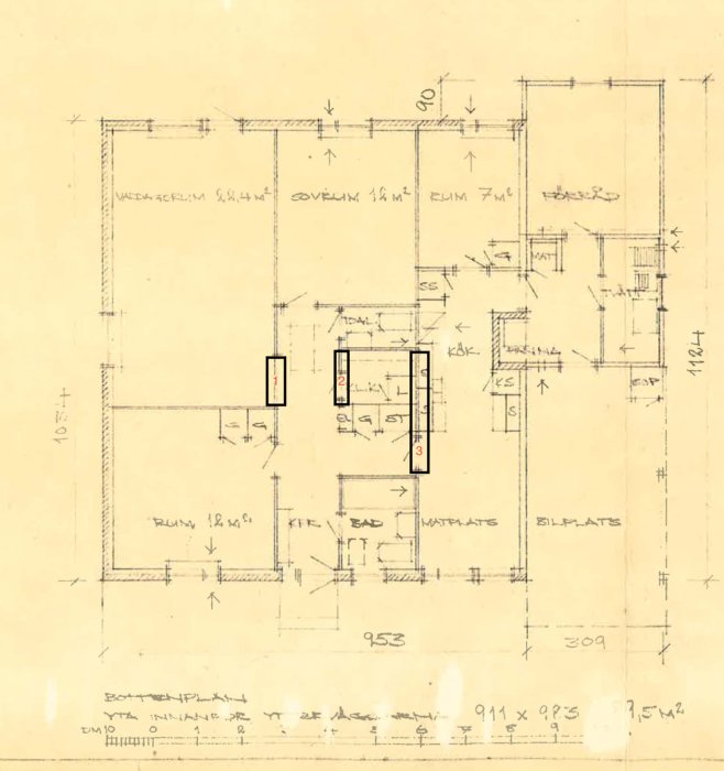
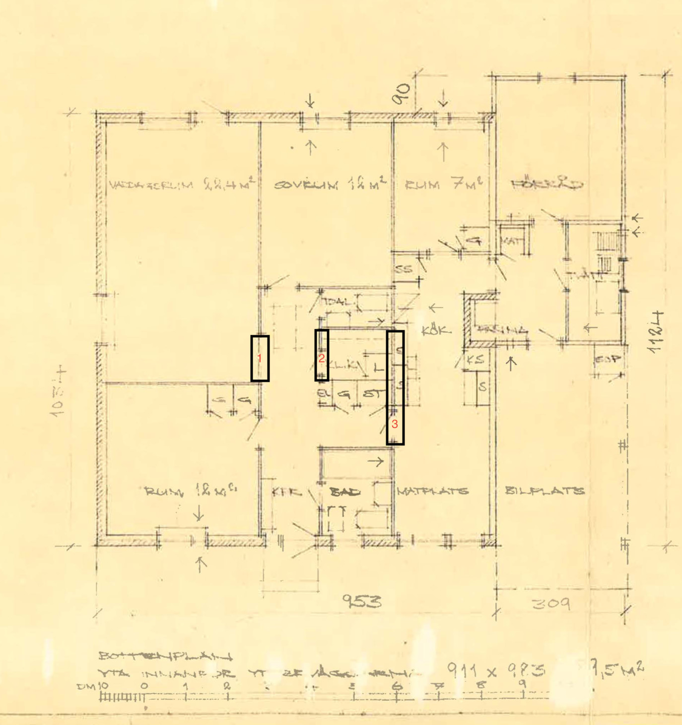
The marked areas in the floor plan are:
1. Current opening to the living room, no beam here.
2. Upcoming opening.
3. Upcoming opening.
Initially, I had planned to replace both wall 2 and 3 with glued laminated timber beams and 2 pillars each, but then I started questioning the need considering how flimsy the interior walls are and whether it is possible to do without one or the other (or both and just sister between the load lines).
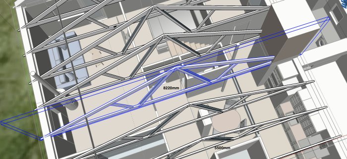
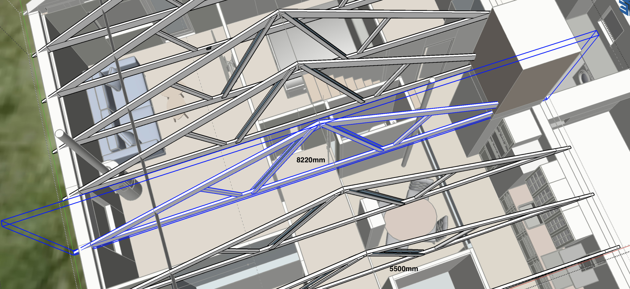
A potential beam in opening 3 would be placed "outside" the small room and would frankly end up under the knee wall closet. A beam in opening 2 feels more necessary in that case because it would drastically reduce the span of the roof truss, which otherwise has a clear span of 8.2 meters, which if we see the lower chord as the load line for the floor joists, is far too long (in such a case, it would be a support that makes it 5 meters from the outer wall and support rather than a span of 8.2 meters; that particular roof truss incidentally rests on the brick chimney, so it has a slightly "shorter" span).
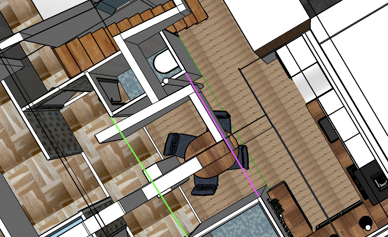
As an illustration of how the roof trusses are oriented, I also attach a screenshot from the SketchUp model I've been working on, where walls 2 and 3 have already been removed.
Hello!
How do you access the attic? Normally, one would count on a useful load on the attic floor of 0.5 kN (about 50 kg) per sqm. You will exceed this, and therefore there is certainly reason to consider some beam replacement, especially in location 3.
Hello!
How do you access the attic? Normally, you would calculate with a useful load on the attic floor of 0.5 kN (about 50 kg) per sqm. You exceed that, so there are certainly reasons to consider some beam reinforcement, especially in location 3.
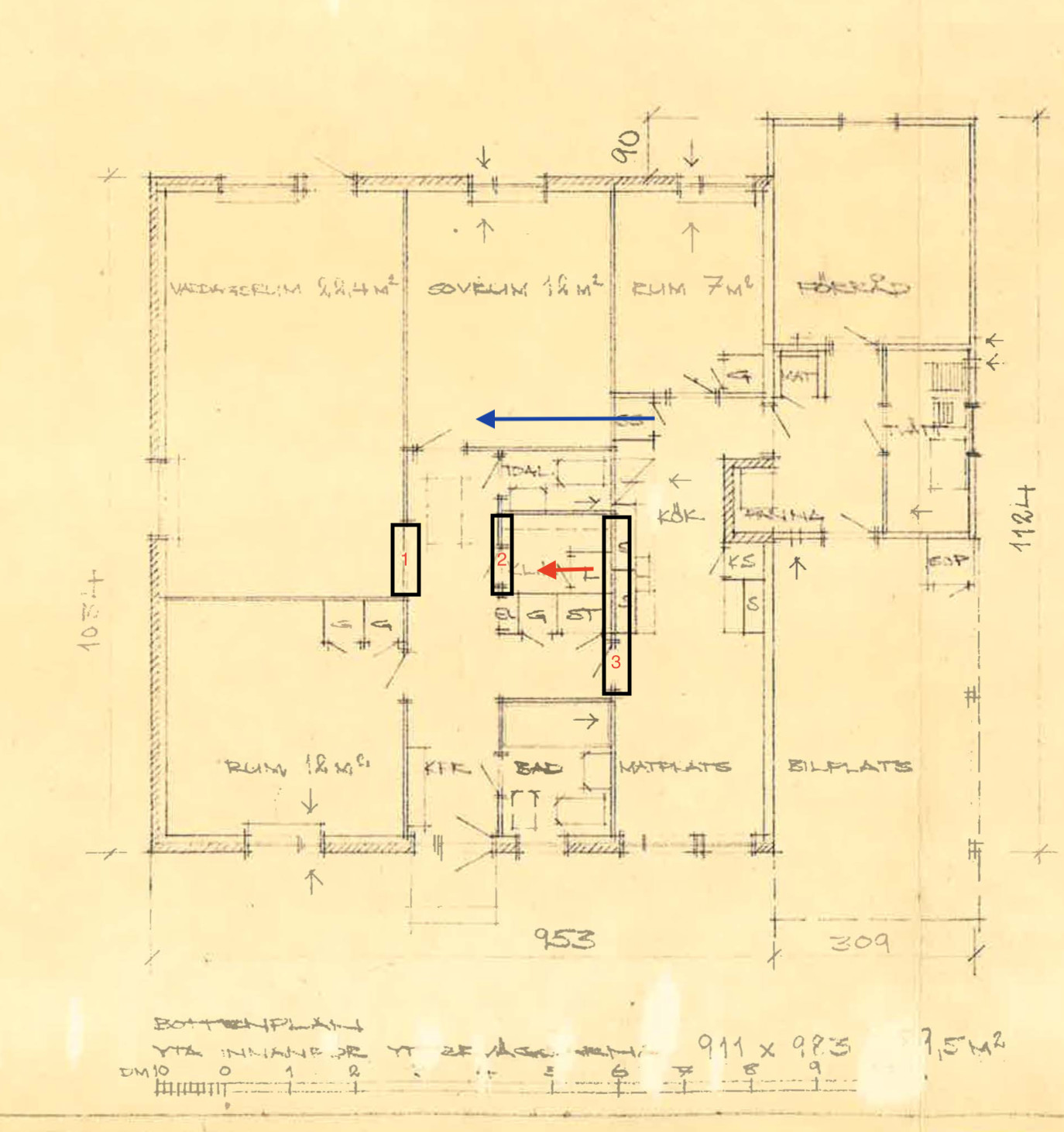
Today, there is a stairwell with a steep foldable stair in what is marked as KLK on the floor plan. (Where I've placed a red arrow on the floor plan below.) The idea is to do as all the neighbors have done and install a narrow, but straight, staircase where I've placed a blue arrow to illustrate the stair direction. It lands between the rafters so it seemed unproblematic.
That's what I suspected. It's probably safest to calculate as if it were a 1.5-story house and reinforce the beams in both. (whereupon I found that 140x225 almost suffices (12mm deformation but well within the breaking limit) or alternatively 90x315 (which manages with 8mm deformation). Does that sound reasonable?
One thought, is it possible to place the beam on top of the underside of the rafters in location 3 (with joints and glue, that is) so that the lower load-bearing arm, which also serves as a floor joist, "hangs in it"? I don't remember those calculations, but then 90x270 or 90x315 wouldn't even be something to consider not using since it's outside in the insulation.
You are absolutely in the right area regarding the dimensions. Placing the beam on top of the underframes should also be able to work. The hang fittings may need to be custom-made by a blacksmith/machine workshop, which rarely tends to be a problem.
You are absolutely in the right ballpark in terms of dimensions. Placing the beam on top of the subframes should also work. The hangers would probably need to be custom-made by a blacksmith/mechanical workshop, which usually isn't a problem.
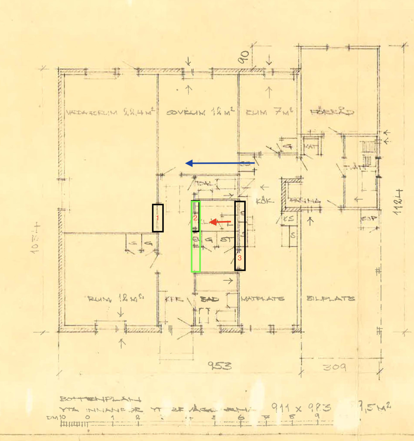
A thought occurred to me as I continued calculating. What do you think about placing a beam at 2 instead of 3 (i.e., green in the images below), but setting it "all the way" so that it is as long as a beam at 2 would be, i.e., even in the existing opening that is not relieved today and has been there since the house was built.
Perhaps I'm making a conceptual error considering that everything above the kitchen (i.e., to the right of "3" in the floor plan) is insulation and a few pipes going up into the attic space, so with self-supporting trusses, it feels like there's no load to take down from that side?
The reason for the consideration is that there will still be a "pillar" in that opening due to the electrical center and the heart of the house for electricity, fiber, underfloor heating, etc., so it wouldn't be difficult to place a pillar in the middle there, and when I calculate, it’s as if there had been a load-bearing wall all the way, with significantly lower dimensions even when I calculate the distance to the load-bearing wall all the way to the outer wall. (90x225 or 115x180 with 1-2mm deflection)