That is, if you add another shelf that is 1000m up, you would get a significant addition and not just 5N more...
In practice, of course, a shelf 1000m up affects quite a lot more, but that's because it's completely impossible to make it 100% rigid.
The higher shelves also affect more if the shelf is overloaded so that the upper screw pulls out slightly from the wall. The more it pulls out, the more it affects how high up you've placed heavy items.
Thank you cpalm.
I tried calculating the force components.
The extreme cases are simple, even though I can't explain with words why the top shelf causes the same pulling force on the upper screw as the bottom shelf.
The middle one applies pressure on the lower screw and pull on the upper screw.
However, I'm stuck on how the forces are distributed for a shelf that is placed at 1/4 of the height. I'm thinking that the distribution is the ratio between the angles or the length of the hypotenuse?
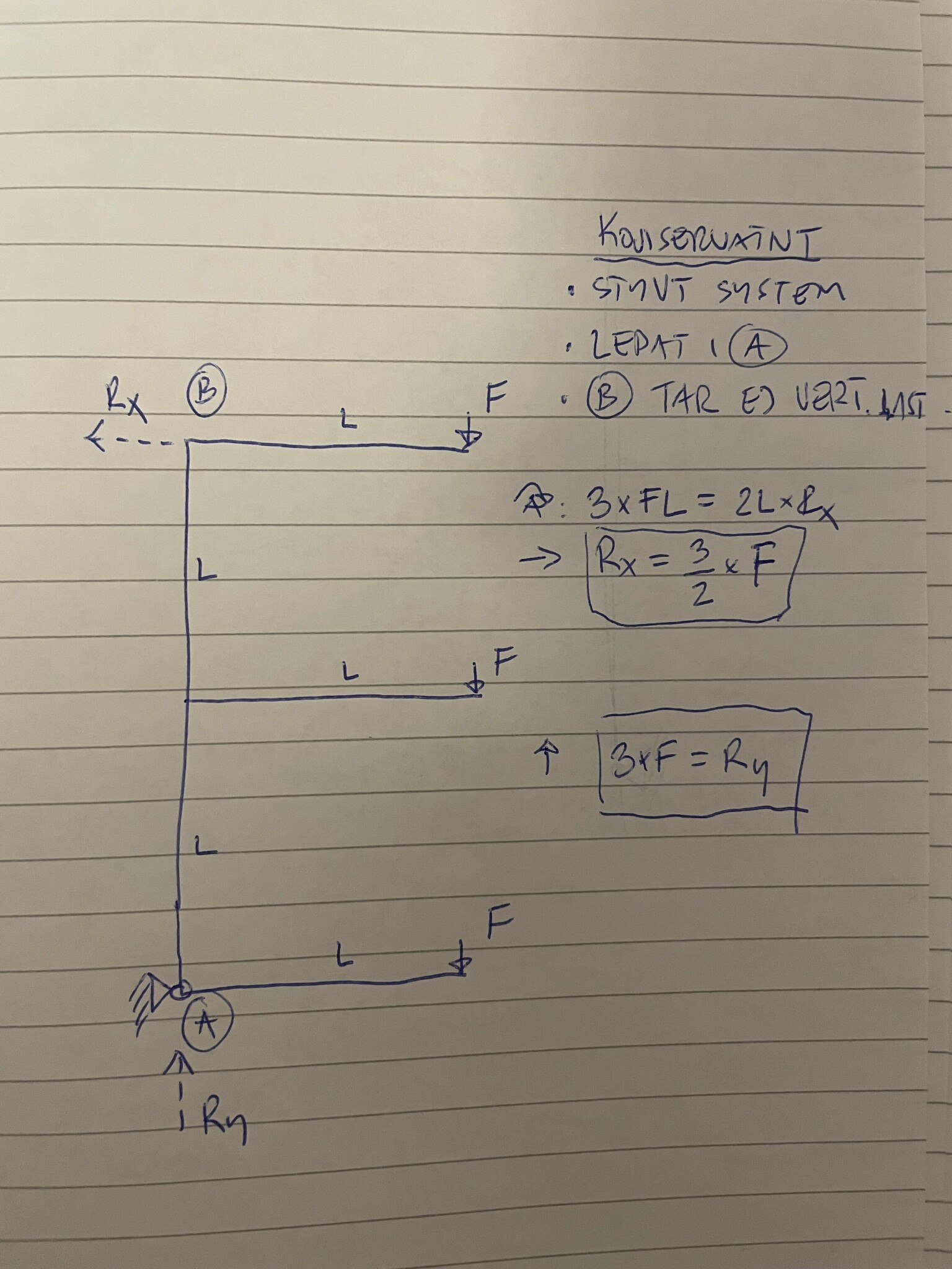
It feels like you're overcomplicating it a bit... Make a conservative arrangement and assume that 1) everything is infinitely rigid, 2) the shelf is hinged at A and all vertical loads are absorbed at A, 3) all horizontal reaction forces are absorbed at B, and 4) L and F in the sketch apply.
Now we have the maximum load, and it is definitely conservative because nothing is rigid in reality and the vertical loads are distributed between the screws in A and B.
Yes, to clarify, my intention was to explain TS's "detour" with the imaginary levers. Once you realize you don't need to think that way, the solution becomes trivial.
With this assumption, it doesn't matter where the shelves are located. You just need to sum them up. But what if there are no sidewalls and you have a shelf at 3/8 height?
Feels like you're complicating things a bit... Make a conservative setup and assume that 1) everything is infinitely stiff and 2) the shelf is hinged at A and that all vertical loads are taken at A and 3) that all horizontal reaction forces are taken at B and 4) that L and F in the sketch apply
Now we have the maximum load and it is definitely conservative because nothing is stiff in reality and the vertical loads are distributed between the screws at A and B
Bo.Siltberg said:
Yes, with this assumption it doesn't matter where the shelves are. You just need to sum them up. But what if you don't have any side walls and have a shelf at 3/8 height?
Not entirely sure I understand what you mean, but it sounds like a statically indeterminate system, i.e., it cannot be calculated with the equilibrium equations. But as I said, it might be that I completely misunderstand...
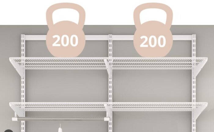
I'm thinking something like this. Apparently, these shelves can handle 200 kg.
What affects it is when the rail bends and puts pressure on the wall higher up than at the bottom. Of course, that's not the only thing that matters. If the wall is uneven or flexible, the result is also affected. If you support the rail at the bottom with a small block so that it doesn't touch the wall between the upper and lower attachment points, you compensate for the deflection, and the result aligns well. You can surely come up with a formula that takes into account the stiffness of the wall and the rail to determine the tensile force on the screw. But if the wall is not flat or if there are studs behind the drywall, it becomes even trickier. The assumption in the first post that the wall and the rail are rigid gives a reasonable value. I think most people install their shelves without doing calculations with the finite element method. And it's a bit above the level of a task like this anyway.
Thank you, I did indeed show a picture of an actual shelf, but I'm still thinking about the original question, how to calculate the extraction force on the top screw using force components instead of torque. This is with the assumptions made about a rigid system, etc. I find it difficult to understand/calculate how the forces are distributed for a shelf at an arbitrary height that is attached at the top and bottom. Perhaps braces/shelf sides don't matter when it is rigid? So it's not a practical problem I'm trying to solve, I just wanted to learn.
Thank you, I did show a picture of a real shelf, but I'm still considering the original question, how to calculate the pulling force on the screw at the top using force components instead of torque. This with the assumptions made about a rigid system, etc. I find it difficult to understand/calculate how the forces are distributed for a shelf on any height attached at the top and bottom. Perhaps struts/sides don't matter when it's rigid? It's not a practical problem I'm trying to solve; I just wanted to learn.
The idea of moments around a certain point is a bit tricky, as what we are after are force balances around that point, calculated to determine the unknown resultant force. We are not interested in any moment in this case.
In some systems, you cannot establish a unique force balance (the distribution of force is not uniquely determined), and you get two or more unknown resultant forces, i.e., a statically indeterminate system. This is not disadvantageous in practice as it often provides good redundancy in a system if, for example, a support were to fail.
A bolted joint takes up either tensile or shear forces or usually a combination of both. In a shelf, as in this example, it is probably impossible to practically pull the screw with sufficient torque for the clamping force between the wall and the rail to become large enough so that the frictional force between them exceeds the self-weight of the shelf, i.e., so the screw does not need to take the shear load. Hence, the conservative approach is to say that only one of the screws takes all the shear load, while in reality, it's likely distributed quite evenly between the upper and lower screws in the example.
Regarding the tensile force in the upper screw, it doesn't matter at what height on the shelf you place your 200kg; what determines it is how far out from the wall the load is positioned.
One might imagine that the 2-dimensional shelf I drew in the sketch is standing on a hard surface and is balancing. Since the shelves contribute some mass, it will not stand upright by itself without you holding it in place sideways. If you add 200kg, you need to hold harder, and moving your 200kg between the shelves makes no difference.
The conclusion is that if you move the screw downward (and keep the shelf and load in the same place), the tensile force in the screw will increase, while if you move it upward, it will decrease, but it still doesn't matter where on the shelf you placed your 200kg.
The interesting question is when you need to attach each rail with three screws; one is placed at the top and one at the bottom, but where do you place the third one and why?! Does it become statically determinate with a third screw? That is, can you calculate how the load is distributed among them?
Click here to reply
Vi vill skicka notiser för ämnen du bevakar och händelser som berör dig.

Bo.Siltberg said: