Yes, it does sound like a bit of work. I hadn't even thought about screwing, but of course, that's an option. However, the underlying problem remains, that is, HEB180 may not be suitable for the new span. Sure, maybe if you extend it with HEB 180 and at the same time reinforce the entire beam with "bandplåt" on the top and bottom flanges. But that's also a bit of work. What I'm trying to do is avoid having to bring in and lift a new beam. They are quite cumbersome and weigh quite a lot...
Welding such a beam is not "rocket science," if there is access around the entire profile it is quite easy, and considering the low stresses the beam is subjected to, you shouldn't need a lot of reinforcement plates.
My mid-floor rests in the middle of the house on a 16m long HEA160 (significantly weaker than your beam) with the largest free span being 5m. Since my beam is so long and continues on each side of this 5m span, I do have a different load case as the beam acts as "fixedly clamped" on each side of this 5m opening.
I have calculated with 200kg/m2 for the load and 50kg/m2 for the weight of the beam itself, I have a good margin against the deflection standard (span/400) but can experience a little bounce if I jump right above the 5m span.
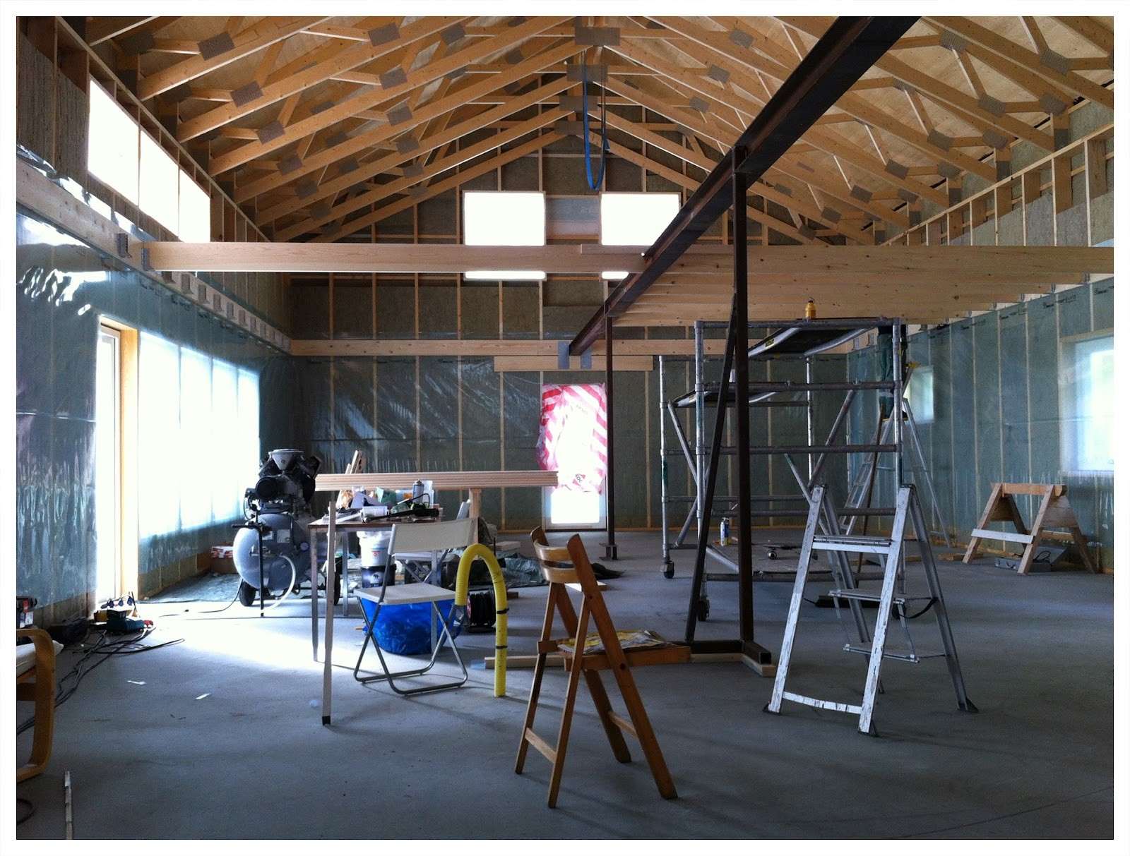
My beam is welded in three places because it couldn't be handled otherwise. I welded it myself with Ø3.2mm P48 electrodes and, of course, proper joint preparation beforehand. I don't consider myself a master welder even though I worked with it in my youth, but I am not the least bit worried about these weld joints. The only extra reinforcements I have welded are web stiffeners above the steel columns.
The image shows part of the beam and about half of the 5m span I described above.
Welding such a beam is not "rocket science," if there is access around the entire profile, it is quite easy, and considering the low stresses the beam is subjected to, one shouldn't need a lot of reinforcement plates.
My mid-floor rests mid-house on a 16m long HEA160 (considerably weaker than your beam) with the largest free span being 5m. Since my beam is so long and continues on each side of this 5m span, I have a different load case as the beam acts as "fixed support" on each side of this 5m opening.
I have calculated with a load of 200kg/m2 and a self-weight of 50kg/m2, I have a good margin against the deflection norm (span/400) but can experience a little bounce if I jump right above the 5m span.
My beam is welded in three places because it couldn't be handled otherwise. I welded it myself with Ø3.2mm P48 electrodes and, of course, proper groove preparation beforehand. I don't consider myself a master welder even though I worked with it in my youth, but I am not the least bit worried about these welds. The only additional reinforcements I have welded are web reinforcements above the steel columns.
The picture shows part of the beam and about half of the 5m span I described above.
Thanks for your input! It's really high and low here. You have an HEA180 (albeit a slightly smaller span) and I was recommended an HEB240 (earlier in the thread). It would be absolutely fantastic if I can extend the one I have, it would significantly reduce the workload for me (or for the person who has to do it).
What you're doing in the picture there looks quite similar to what I need to do, and just off the cuff, I would say it looks like your wooden joists are also longer than my 3 and 3.5 meters.
I only have a HEA 160 and the beams (220x45) are 4m long. Now my upper floor is more like a loft and I can accept that the joist floor has a slight deflection, but as I said, I meet the deflection standard brilliantly.
I spoke with the "local" steel company and it's not too expensive for a slightly more substantial beam (HEB220 or 200). Even getting it delivered with a crane isn't particularly expensive, BUT then you have to get it in place. It was probably easier when they put the one that's there, before the house was built on the foundation...
The solution with plates is to make welding easier, allowing for smaller fillet welds. Pure power transmission, so no reinforcement plates. Sure, you can weld without plates, but it requires more of the weld. Depending on where the joint is placed, it's not as sensitive with joints in a continuous beam as in Gabbe1's case. This creates a so-called Gerber system. In a freely supported beam like in your case, it's more sensitive. A continuous beam also doesn't deflect as much, which is why Gabbe1 can manage with a much smaller beam. I have a couple more suggestions: Check if an IPE beam could be an alternative, they have thinner material thickness, but you can compensate with a higher beam = lighter beam overall. Suggestion 2: Screw together 2 U-profiles back-to-back, then you can create your own I-profile which is even easier to handle. Unfortunately, I can't give you any dimensions from where I am now, but maybe someone else on the forum can help.
Aha, a few clever ideas! Thanks for that! It looks like UPE beams result in less material (less tf and less width but a little more tw) for the same height, so maybe easier to install (since they can be set up in two steps) but then give poorer "load-bearing capacity." I actually don't want much more height. I currently have about 210-215 cm from the finished floor to the beam and don't want it to be too low if possible. I understand that height significantly affects how much it "bears" (^3 I believe?), but I don't know how much taller an IPE needs to be.
Can't help but consider double HEB180 next to each other now that one has been introduced to innovative thinking
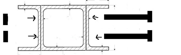
Maybe UPE-KKR-UPE screwed together? (in other words, a lying U, square profile, and then another lying U)?
(edit: I realized it's difficult to have nuts inside the square profile, so now I'm thinking through bolts. I realize now that I can't remove the old image... oh well, the one with long bolts is what I had in mind)
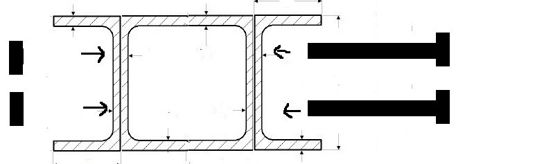
You might then have a UPE (200mm high and width 80mm), a KKR (200mm high, 100mm wide, thickness 8mm), and then another similar UPE. It totals 260mm wide and (of course) 200mm high. The question is whether together it is better than a 200mm HEB? (easier to handle, you can lift one at a time),
One could then have a UPE (200mm high and 80mm wide) a KKR (200mm high, 100mm wide, thickness 8mm) and then another identical UPE. This totals 260mm wide and (obviously) 200mm high. The question is whether it is altogether better than a 200mm HEB? (it becomes easier to handle, can lift one at a time),
You'll need to use the Steiner's theorem to calculate when you combine different types of beams.
Since the cross-sections are symmetrical and the center of gravity is at the same level, there is no need to use Steiner's theorem; you simply add the cross-sections. Note that a KKR does not look exactly like you have drawn in reality. The bending radius makes the corners heavily rounded, so it may not be possible to place the screw as you have drawn. Instead, use a hot-formed profile (VKR), the bending radius for the corners is much smaller for them (although not as sharp as in your sketch).
A bit skeptical about a box beam altogether. To achieve any interaction between them, you need to tighten the screw hard, questioning whether you can tighten the screw as much as required without the beam buckling. In that case, it is better to drill holes in the web of the UPE and the box beam so you can reach to place a nut inside. If you have someone to thoroughly calculate the whole thing, it might be reasonable to manage with 2 UPE240 (which corresponds to nearly the same moment of inertia as an HEB 220).
I thought that the screws would just hold the package together, so to speak.
I imagined that you just "add" the moment of inertia for each additional beam if they lie next to each other, but maybe it's not that simple?
I feel like I'm on thin ice, grateful for the feedback! One should find a little short tutorial book on this subject, it's quite interesting.
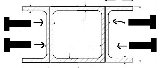
The problem is that the load must be evenly distributed over the built-up cross-section, or alternatively, it must be so well joined together that it acts as a homogeneous cross-section. In your pictures, it looks like all the load will come to the middle of the box beam, so the forces must be transferred via the screws to the UPE profiles. The screw will also help prevent the cross-section from buckling (When a flange is compressed, a tall beam will tend to bend sideways). If you can somehow ensure that the cross-section is evenly loaded, i.e., you have contact with all 3 profiles when you apply the load, then theoretically you do not need screws if you can also show that the 3 separate cross-sections do not buckle out. Probably hard to achieve in practice, so I would put some screws in anyway. I do not know of any "short" guidebook.
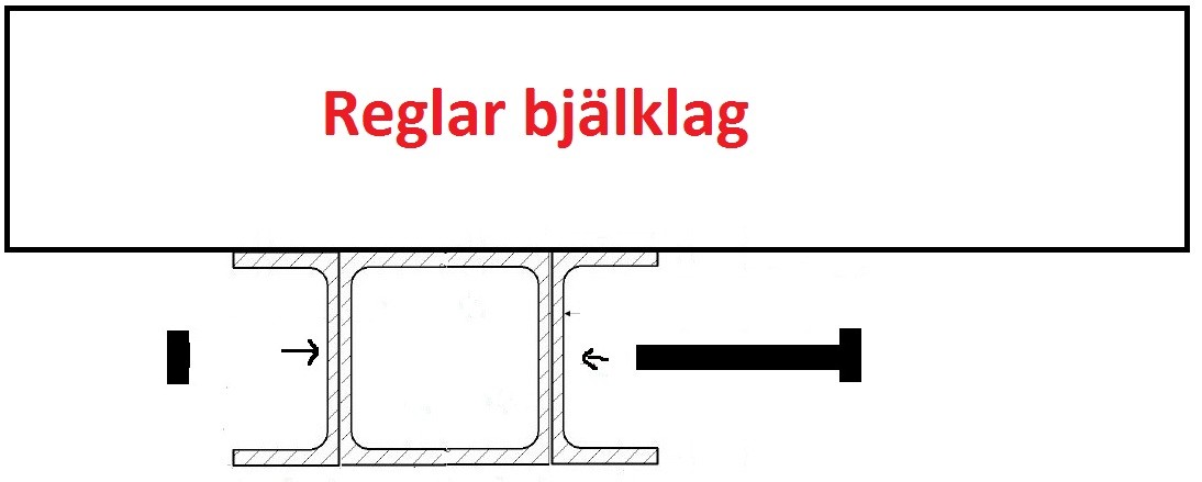
Well, the force is probably evenly distributed. The beam is under the joists in the layer above, and they should press equally on all "parts" of my Frankenstein beam. I don't think that's what you meant above?
Like this:
Vi vill skicka notiser för ämnen du bevakar och händelser som berör dig.

")