I am in the process of building a garage with an upper floor. The slab is cast, and I am now pondering the floor joist dimensions. There is a lot of great expertise here, so I thought I’d try here before talking to a structural engineer.
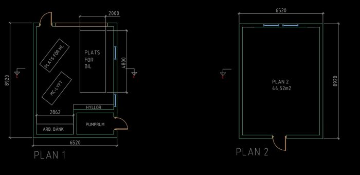
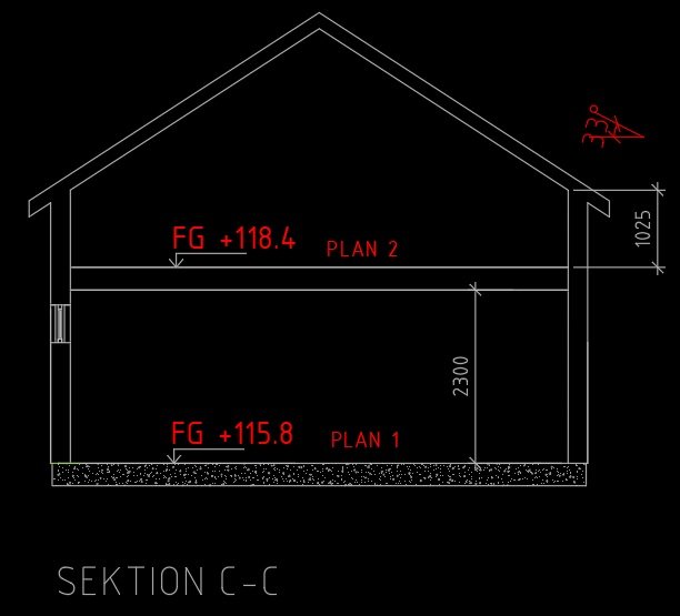
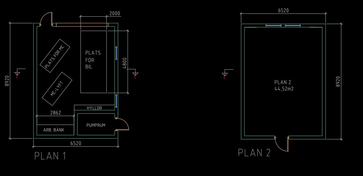
Here's what the plan and section look like;
My thought is that the support will be on the outer walls (of course) and also on a beam in the middle. To shorten the span a bit, it is possible to support the beam in the wall of the pump room. From the pump room to the garage door, it's about 6.5m.
If I enter three supports in the Swedish wood dimensioning help for indoor floor joists, I find that I could manage the floor with construction timber 45x170 C30 c/c 600. But what beam will I need in the middle? I can't find a good dimensioning tool for, for example, glulam or steel beams there.
Then, of course, there is the question of the beam's attachment and its support above the garage door, but I think it's easiest to find out the beam size first.
Does anyone have any tips on dimensioning tools or how to think?
There is a lot you need to check, many parameters, equations, etc., if you are not familiar with the design requirements. A brief description of the thought process is:
The beam will be loaded by point forces from each floor joist (which you can simply consider as a distributed line load). You will likely have two supports on which the beam rests, and depending on the attachment, you can consider the beam as simply supported or fixed.
Once you have determined the forces in the beam, you need to convert them into design loads, and then use equations to check, among other things, the moment capacity, shear capacity, pressure on the beam from the supports, and deformations.
There is quite a bit you need to check, many parameters, equations, etc., if you are not familiar with the dimensioning requirements. A small description of how you should think is:
The beam will be loaded by point forces from each floor joist (which you can simplify as a distributed line load). You will likely have two supports where the beam rests, and depending on the mounting, you can consider the beam as simply supported or fixed.
Once you have derived the forces in the beam, you need to convert them to design loads and then use equations to check, among other things, the moment capacity, shear capacity, the pressure on the beam from the supports, and deformations.
Here is some guidance if you are interested:
[link]
Otherwise, I do not recommend designing things yourself if you do not have previous experience. I don't know if there's a free program available.
Hi!
I'm thinking of starting by trying a bit myself, so I get some preliminary sizes, etc. I draw most of it myself (a lot of CAD but mostly electrical and a bit of architectural design), which someone will then check.
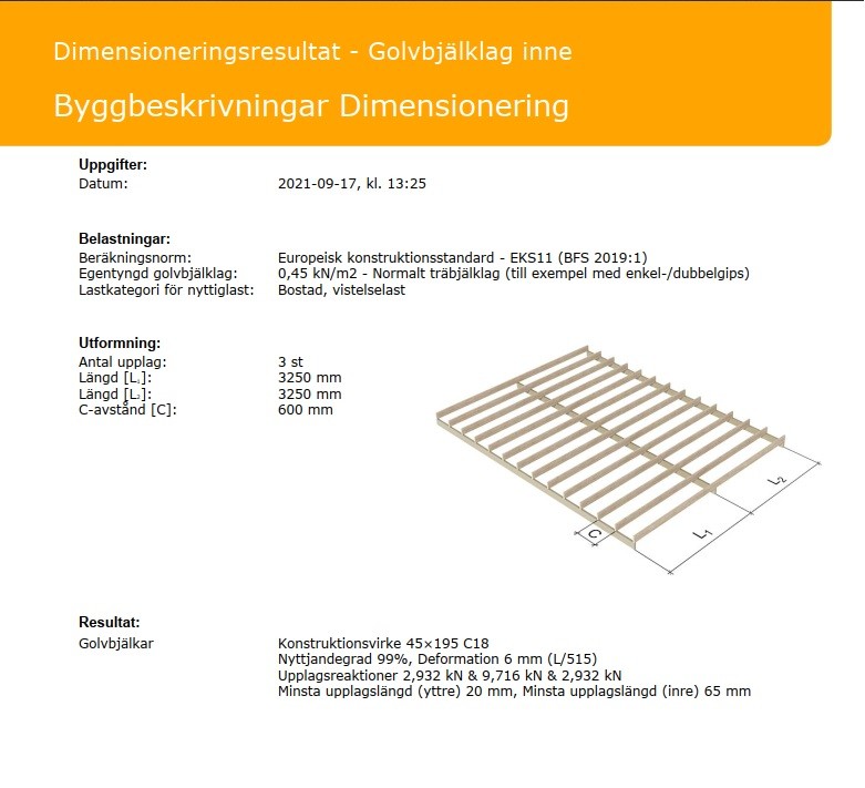
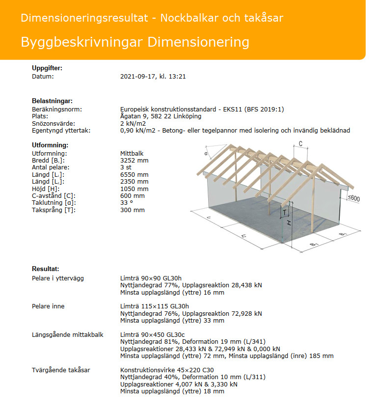
Regarding how I determined the size of the floor structure, I used Svensk Trä's dimensioning tool and got the following;
I changed from 45x170 to 45x195 to have a bit of margin, and it seems to work.
Then I assume the beam will also be supported in the wall to the pump room. That is, 3 supports.
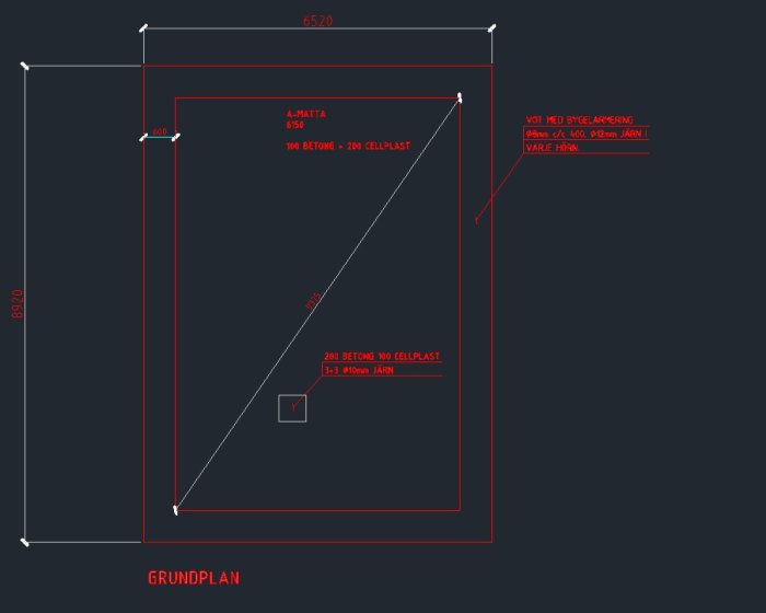
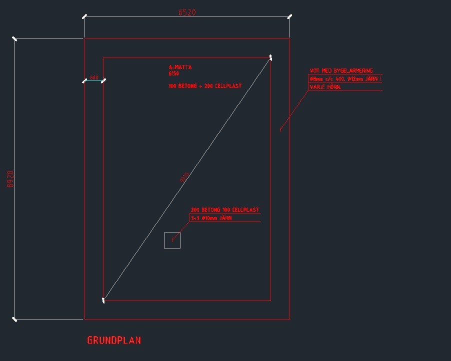
The concrete slab will be strengthened with a base of about 700x700 under the inner corner of that wall.
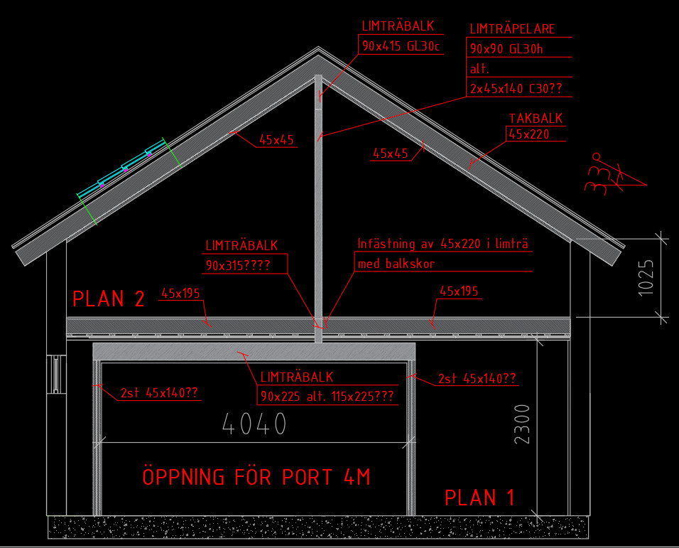
I am also reviewing the second floor, which will have a ridge beam where I also plan to "support" with a pillar in the same position as the inner corner in the pump room;
In other words, I try to draw it up to explain my thought process so someone can check it afterward. I think it's good to have at least tried to think it through beforehand.
Load: 250 kg/m2 with half loading the beam = 52,000 N distributed load.
Acceptable deflection: Span / 300 = 22mm
This means you need about 4000 cm4 in the moment of inertia.
Choose, for example, HEA 220 which has 5410 cm4
It will definitely work with IPE 240 as well, even though it only has 3892 cm4
Make sure the concrete slab is built to handle the point loads from the columns.
Hi,
Thanks for the response. If possible, I would like to avoid metal beams. Glulam or lightweight beam/masonite beam is preferred as I think it will be easier to work with. That said, metal is not excluded...
I would like to reduce the height of the floor structure a little. Does the beam change if you choose to attach the floor structure with joist hangers instead of laying it on top of the beam?
I would like to reduce the height of the floor joists a bit. Does the beam change if you choose to attach the floor joists with joist hangers instead of placing them on top of the beam?
It doesn't matter if you place the floor beams on top or attach them to the sides of the beam. If you choose glulam, the beam will be around 115x450mm, so it might be a big advantage to attach the floor beams to the sides; otherwise, the glulam beam will protrude unreasonably far. It is for that reason (about half the build height) that steel can be a good alternative in an intermediate joist.
It doesn't matter if you place the floor joists on top or attach them to the sides of the beam. If you choose glulam, the beam will be around 115x450mm, so it might be a great advantage to attach the floor joists on the sides; otherwise, the glulam beam will hang down unreasonably far. It's precisely for that reason (about half the building height) that steel can be a good alternative for an intermediate floor.
OK.
115x450 would be tall. The problem is that I would like to have a door under the beam, and I will need some form of beam over the door. My working hypothesis was that 90x315 glulam would be sufficient in the floor structure and then a 90 or 115x225 over the door;
But I might have to bite the bullet and go with steel.
Do you happen to have a drawing of the slab and how it is reinforced, the quality of the insulation under the slab, and the type of ground the garage stands on? This sets limitations for how the bearing of the floor and roof can be designed.
A common design to save height is to recess a steel beam, type HEA, and lay the wooden joists on the bottom flange.
The transition over the gate will need to be executed in steel as it must support a very large portion of the roof. Is roof tile intended?
I might put steel over the garage door as well. That is a smaller issue since that span won't be so long (read: heavy).
I'm considering whether to abandon the ridge beam on the upper floor and use scissor trusses instead, so the weight is transferred to the side walls instead.
Hmm. With a steel beam over the garage door, possibly a 415 high glulam in the floor structure might fit. The problem could be the clearance height that the garage door (overhead door) needs above the opening in the facade...
Doesn't the ceiling height on the upper floor get quite limited with framework trusses?
Even though the collar beams lower the height somewhat, it becomes a bit more spacious with framework trusses if you don't incorporate the collar beams, that is.
Vi vill skicka notiser för ämnen du bevakar och händelser som berör dig.