Hello Granngubben!
Thank you for your response. It was very kind of you to help me with this. Is it such a "high" profile to achieve a maximum of 5mm deflection? Well, I'll be damned. I thought it would approach 0mm at that height. I was hoping to be around 50mm in height to stay under 5mm. Perhaps a silly question but I assume you've calculated on a standing profile?!
// Himneck
Maybe a dumb question but I assume you calculated on a standing profile?!
// Himneck
Yes, I assumed a standing profile (load and deflection in the beam cross-section’s stiff direction).
You need a moment of inertia I of about 504,000 mm4 to not exceed 5 mm deflection at the end of the beam. Rectangular tube KKR80x40x3 has I = 523,000 mm4.
Hello Enk Project!
It will be completely concealed. It is part of a sliding door construction. The principle is the same as in large free-hanging industrial lattice gates. Preferably, I don't want the height measurement to exceed 50mm. I can post a principle sketch when I get home today. There is also a possibility to counteract deflection with a tension wire.
Yes, I assumed a standing profile, (load and deflection in the stiff direction of the beam cross-section).
You need a moment of inertia I of about 504,000 mm4 to not exceed 5 mm deflection at the end of the beam. Square tube KKR80x40x3 has I = 523,000 mm4.
I thought I would easily get away with just having confirmed that a 50mm beam at the bottom of the construction would suffice to keep me within the limits and let the rest of the construction stay out of it, but I think it's easiest if I come back with a complete sketch of what I want to construct. The remaining parts of the construction counteract the deflection, so maybe I can manage with a weaker beam if I'm lucky!
Hello Granngubben!
The sketch is on the way. We experienced a power outage on Saturday which resulted in my computer crashing completely. I think I've fixed it now, so I should be able to send a couple of pictures this evening if everything goes well!
Here are a couple of sketches of the construction.
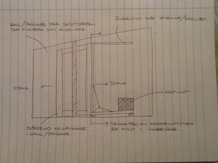
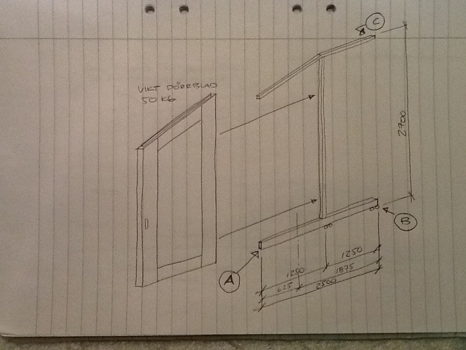
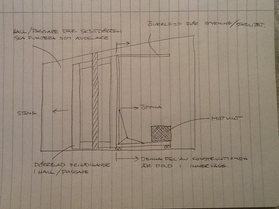
The deflection of the lower beam in the tubular construction should be kept under 5mm at point A to be able to counteract it in the attachment of the beam at the other end, point B. Unfortunately, points B and C cannot be linked to stabilize the construction.
What is visible to the left of the counterweight is a tension wire as an additional option to compensate for the deflection.
Then we understand what you plan to build. A few considerations:
In your first post, you mention 100 kg load. The sketch shows a door leaf of 50 kg.
The door leaf should be able to function as a rigid board. If the door leaf is attached to the beam to prevent beam bending between 1250 and 2500, you get a completely different load case. Then you can manage with a lower beam.
Neighbor:
I got a preliminary weight from the carpentry shop of almost 100kg, but when it was delivered, it only weighed 49kg, which is of course positive. I thought I had already mentioned this in the thread, but I hadn't!
Sounds good if the blade works as a stiff panel. The vertical beam and the overlay will be screwed into the door leaf, but at the bottom, it will be a bit trickier to access and fasten the 2500 beam to the bottom leaf. The entire steel frame comes in parts and is assembled on-site inside the inner wall, which hides the sliding door when open. If it's not a must for stability, I would prefer to avoid fastening at the bottom.
Oh well, hopefully the price of the door was also halved
I understand that you don't want to attach the door to the beam, but maybe you can get a mounting point at the beam end (towards the door side).
The proposed wire bracing is a good idea that gives you the ability to adjust the door's tilt (it can be even more effective if the mounting point on the beam is placed closer to the counterweight).
If the counterweight loads the beam, as it appears in the sketch, it compensates for some of the deflection from the door's weight.
a pity I didn't sketch my "counterweight" doors.
basically just a few pulleys and a larger counterweight in the door itself.
at least half the size of your construction
Neighbor guy:
Unfortunately, the price is affected. However, VAT was added.
I can probably get a couple of screws in the bottom edge with some work.
The idea with the wire is primarily to be able to fine-tune the angle of the door leaf. I can place the wire attachment at the very back by the counterweight if needed.
There is also another possibility as an alternative to the counterweight, which is to let the rear wheels "hang" on the top edge of the rail. The rail is an upside-down ceiling track for hanging sliding doors, so it is actually made exactly for this type of load.
Vi vill skicka notiser för ämnen du bevakar och händelser som berör dig.

")