5,054 views ·
15 replies
5k views
15 replies
Calculation of glulam, open up load-bearing (?) wall.
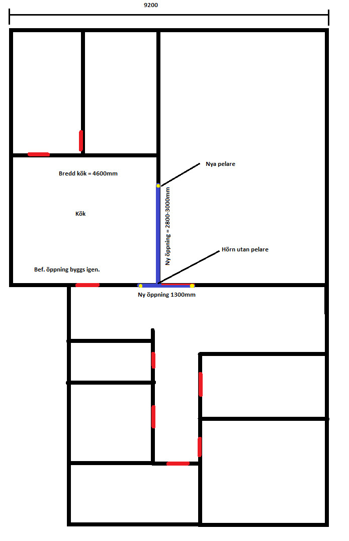
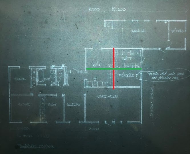
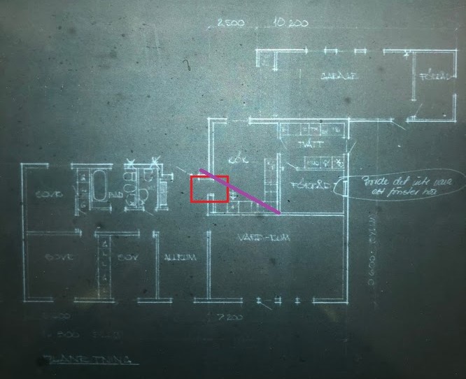
We are planning to renovate the kitchen in the spring and at the same time open up between the living room and kitchen for a slightly more open floor plan, attaching a picture of my idea.
Conditions are as follows; single-story house, slab on grade with raised floor, low slope tar roof (about 10 degrees, hipped), 12mm hardboard ceiling.
I have looked at some different tools available online, but there's no option for single-story houses, only 1.5 & 2-story houses.
Is my plan feasible? I'm a bit curious about how to solve the "corner" where the presumed glue-laminated beams are located.
Do you screw the beams together? Beam hanger?
Red lines = Existing openings/doors
Yellow dots = New posts
Purple = New opening
Thanks in advance")
Conditions are as follows; single-story house, slab on grade with raised floor, low slope tar roof (about 10 degrees, hipped), 12mm hardboard ceiling.
I have looked at some different tools available online, but there's no option for single-story houses, only 1.5 & 2-story houses.
Is my plan feasible? I'm a bit curious about how to solve the "corner" where the presumed glue-laminated beams are located.
Do you screw the beams together? Beam hanger?
Red lines = Existing openings/doors
Yellow dots = New posts
Purple = New opening
Thanks in advance

I would rather see an original drawing. It is difficult to draw any conclusions from your sketch. Dimensioned and to-scale drawings are best. A one-story house can have free-spanning trusses, eliminating the need for load-bearing beams. Sectional drawings are therefore important.
The problem is that original drawings are missing.J justusandersson said:
The house was built in 1974 and is a module house, unsure of the manufacturer.
Are there other ways to find out if the trusses are free-spanning?
If you have access to the attic, photos from there can explain a lot. External images can also explain some parts, especially describing the roof structure overall. The house has some form of angle solution that needs to be understood.
It's not quite easy to access the attic, we have a couple of attic hatches where we might be able to take a few pictures from.J justusandersson said:
I have also emailed the municipality to see if they still have any drawings.
I'll get back to you
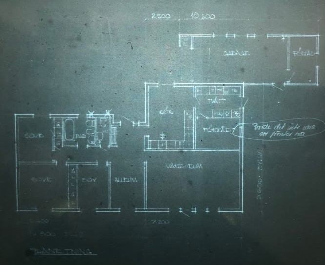

If you can read drawings, they actually say quite a lot. Among other things, they explain the outer roof shape. The house is L-shaped with a low-sloping hipped gable roof. Even the corner part of the L is hipped. Therefore, no external pictures are needed, but rather some photos from the attic showing the roof trusses. With a bit of luck, you have free-span trusses that do not require any beams.
There, I've made an attempt to take some pictures.J justusandersson said:If you can read blueprints, they actually say quite a bit. Among other things, they explain the outer roof shape. The house is L-shaped with a low-pitched hipped gable roof. The angled section of the L is also hipped. Therefore, no external images are needed, but some photos from the attic showing the trusses would be helpful. With a bit of luck, you have self-supporting trusses that don't require any load-bearing beams.
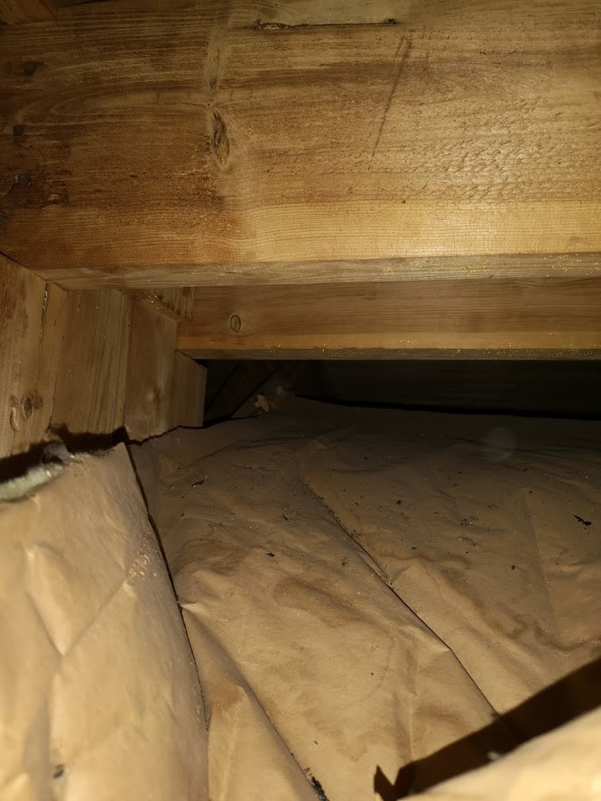
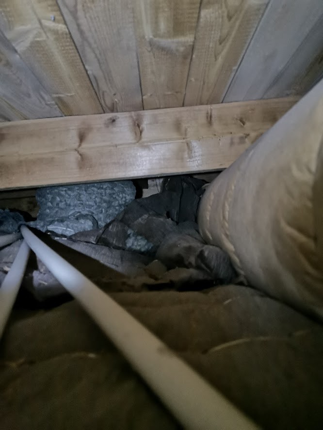
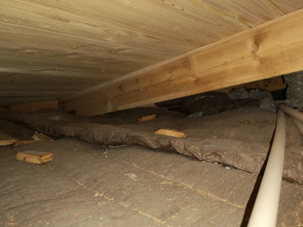
Hope they help a bit, the insulation you see in pictures 3 and 4 by the ventilation duct I unfortunately couldn't push down.
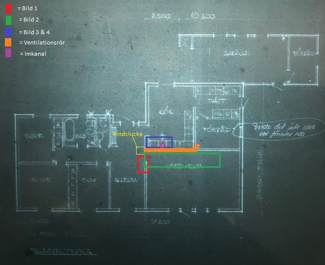
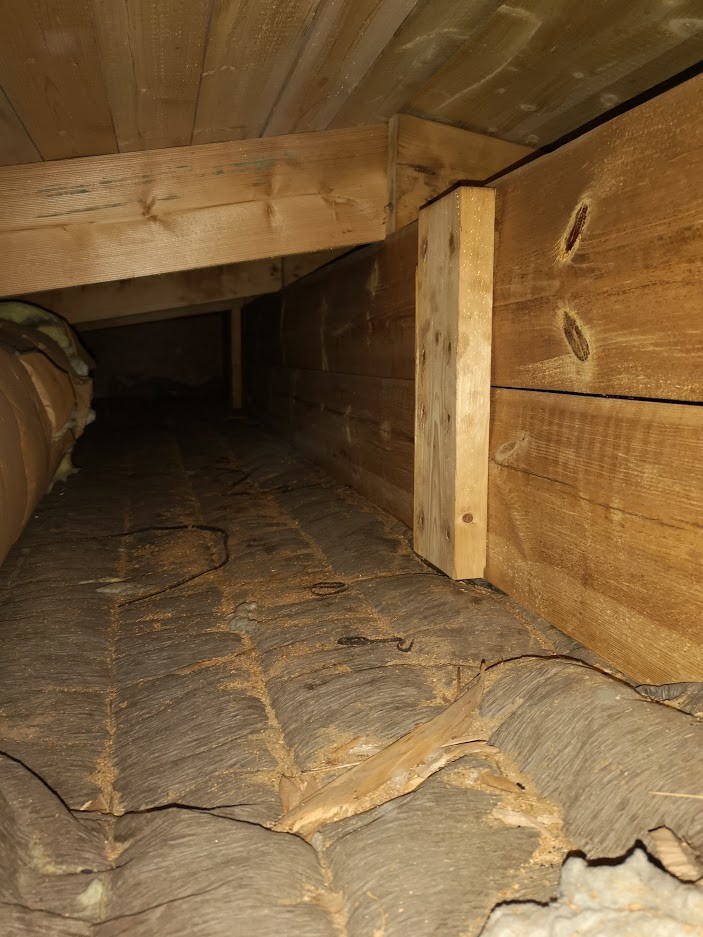
Picture 1:
Picture 2:
Pictures 3 & 4:
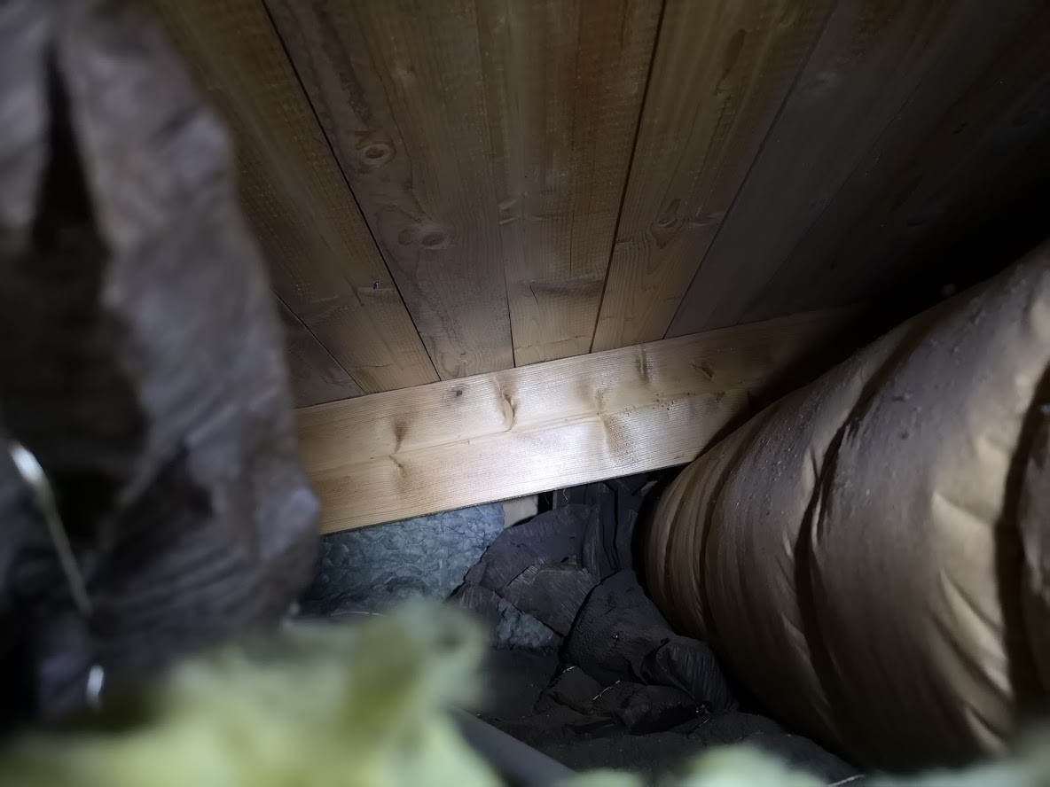
You've done a great job! Marking the camera angles on the drawing made everything much more useful. There are no truss rafters, but the rafters are instead supported by ridge beams. In image 2, it's clearly visible that the ridge beam above the living room is aligned with the heart wall in the other part of the house. In fact, much suggests that the openings you mentioned in your first post are feasible without reinforcements. I would like to have a few more uncertainties clarified. Is there a beam in the kitchen ceiling that runs parallel to the exterior wall?
ThanksJ justusandersson said:You've done a great job! Marking the camera angles on the drawing made everything much more useful. There are no truss roofs, but the trusses are supported by ridge beams. In picture 2, you can clearly see that the ridge beam above the living room aligns with the center wall in the other part of the house. There's a lot to suggest that the openings you mentioned in your first post are feasible without reinforcements. A few more questions I would like to have clarified. Is there a beam in the kitchen ceiling that runs parallel to the outer wall?
I'll take a look at it tomorrow. Couldn't see any more beams but I'll try to move the insulation more
I assume you mean the outer wall facing north? (The garage)
The wall that separates adjoining spaces in the laundry and storage should have a counterpart in the form of a beam across the kitchen. If so, it should be visible in the kitchen ceiling.
I understand. When I look at Picture 2 on the computer, I think I see a beam further in that seems to line up with the wall separating the kitchen and storage/laundry room, but I'm not entirely sure. (Red marking) I assume you mean a beam that would lie roughly like the Green marking.J justusandersson said:
I'll give it another try tomorrow and see if I can find something useful.
Edit: Could the red marking also be a ridge beam?
Last edited:
Unfortunately, I can't read your attached image. We're hoping for better luck tomorrow.
Here is the image I attached in the previous post if it still isn't visible:J justusandersson said:

I tried taking more pictures today, but it's not easy, I've stretched in as far as I can to get a good picture. Unfortunately, it is impossible to see if there is a beam according to the green marking.
The ceiling will be torn down in the kitchen during the renovation, so one simply has to wait until then to ascertain if there is a beam there
The red marking is what we see in the pictures, the purple line is a crossing roof truss, I assume that's where the valley gutter is.
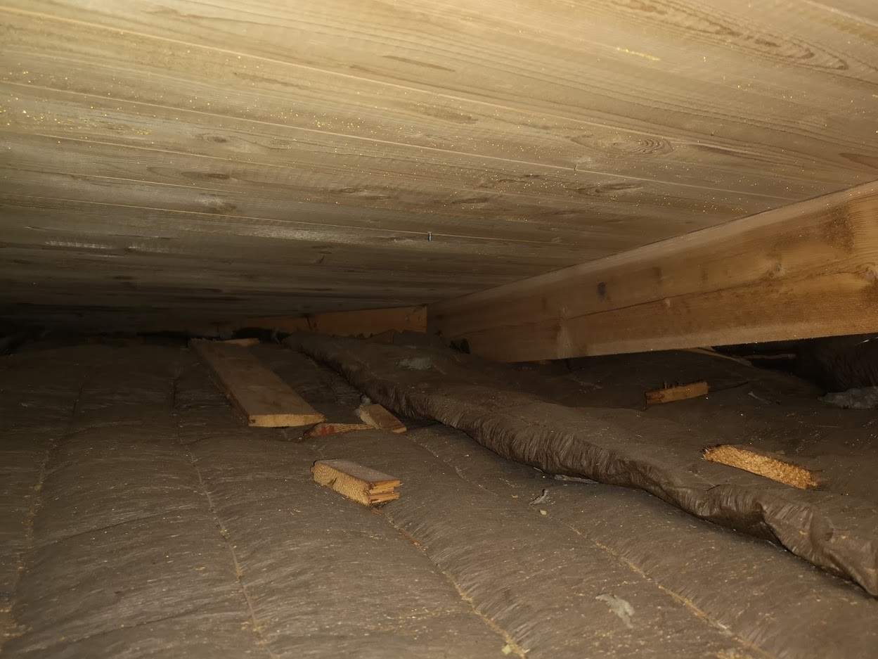
Yes, there should be a ridge beam along the red line as well. There should also be something resembling a beam along the green line that helps support the roof beams belonging to the main section. The purple line is a valley rafter in the intersection between the roof shapes in the inner corner of the L. Additionally, the hip roof complicates things. It would be best if you could also find a roof plan.