Thank you for the response, I think it might be a solution to run the insulated brine pipes in conduit pipes so that you can get airflow around them?
No, I don't believe that at all. I might have been a bit unclear, but the problem with the freezer room is when it cools down the inside of an exterior wall. In a floor structure, as mentioned, the surrounding RH should be sufficiently low to ensure that the dew point falls within the pipe insulation.
Ok, why don't you believe that? If warmer air moves after the surface of insulation, it should raise the temperature there and keep the dew point inside, right? Then you should also be able to insulate the rest of the floor structure.
How do you mean there are controls on RH there? Warm summer days, the RH should be about the same inside and outside, right?
Ccpalm said:
No, I don't believe that at all. Maybe I was a bit unclear, but the problem with the cold room is precisely when it cools down the inside of an exterior wall. In a floor structure, the surrounding RH should, as mentioned, be sufficiently low to ensure that the dew point is reached in the pipe insulation.
Well, there is nothing wrong with the principle itself. I rather see the practical difficulties - the flow resistance becomes quite high. How do you create overpressure? Energy consumption? How do you avoid leakage? Noise? Unwanted air movement in the house? How do you prevent blockage, etc.? Simply a too complicated solution.
How do you mean that you have control over RH there? Warm summer days, wouldn't the RH be about the same indoors and outdoors?
Generally, you're around a maximum of 60-75% indoors. So you always have a bit of margin.
I was on the Energy 2D website and read a bit. I don't think there's any reason to question the calculation software. However, it is quite advanced as it also accounts for how surrounding air moves. For a simple stationary heat conduction analysis, including air movements is overkill. The basic heat conduction equations are very simple and easy to solve. However, the same cannot be said for fluid dynamics equations. I don't work with it myself, but I have colleagues who do, and it requires a lot of knowledge and skill to perform good simulations with CFD programs. Since Energy 2D includes some type of CFD analysis, I think it's quite easy to make mistakes when setting up your model, resulting in strange outcomes. Today's computational programs, both in structural mechanics and fluid dynamics, are highly competent and can solve very large and complex problems. I've seen a lot of different analyses in my work, but very often you get more out of it by taking a few steps back and creating models as simple as possible, where it's easy to interpret and understand the results.
I find Energy 2D exciting; I'll see if I have time to install it and explore how it works.
It's possible that I don't understand the extent of the problem with the simulation and sure, I'm groping a bit in the dark but there aren't an unreasonable number of knobs to turn in Energy 2D. I've simplified the model recently and use boundary conditions (25 degrees constant temperature).
/Fredrik
hlph said:
I was on the Energy 2D website and read a bit. I don't think there is any reason to question the calculation program. It is, however, quite advanced where it also considers how surrounding lift moves. For a simple stationary heat conduction analysis, it is overkill to include air movements. The basic heat conduction equations are very simple and easy to solve. However, that cannot be said about the equations for fluid dynamics. I don't work with it myself, but I have colleagues who do, and it requires a lot of knowledge and skill to make good simulations with CFD programs. Since Energy 2D includes some type of CFD analysis, I think it's quite easy to make mistakes when setting up your model, and the results become strange. Calculation programs today, both structure mechanics and fluid mechanics, are highly competent and can solve very large and complex problems. I've seen many different analyses in my work, but very often you get more out of it if you take a few steps back and make the models as simple as possible so it's easy to interpret and understand the results.
I find Energy 2D exciting, I will see if I have time to install it and take a closer look at how it works
Hmm, good comments, I haven't thought much about the practical aspects
My initial idea was that it would become a natural draft so the air would "fall" down from the bedrooms, coming well-cooled by the pipes, to the laundry room where the pump is located and where there is also exhaust air.
If you don't want "Unwanted air movement," you can make sure the air goes up through one pipe and back in the other. In that case, you probably have to set the air in motion with some sort of fan, like a duct fan at the T-junction.
The flow shouldn't be a big problem; partly I don't think it needs to be that large, and you can lay a 62mm (32+2*15) insulated hose in a 110 conduit.
You'll probably have to live with noise and energy consumption
This is mostly a belt-and-braces solution; of course, it would be better if one could feel calm and confident with just insulating.
Ccpalm said:
Yes, there's nothing wrong with the principle itself. I see more the practical difficulties - the flow resistance becomes quite high. How do you create overpressure? Energy consumption? How do you avoid leaks? Noise? Unwanted air movement in the house? How do you prevent it from getting clogged, etc. An overly complicated solution, simply.
Generally, you're around a maximum of 60-75% indoors. So you always have a bit of margin.
May I ask what you and your colleagues do for work?
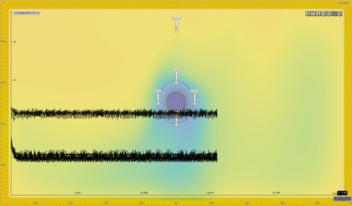
Below is my last run, much more stable but still not a good result (compared to paroc). My model is here: [link] if you're interested.
It's possible that I don't understand the extent of the problem with the simulation, and certainly, I am fumbling a bit in the dark but there aren't too many knobs to turn in Energy 2D. I have simplified the model recently and am using boundary conditions (25 degrees constant temperature).
[image]
/Fredrik
I hope I'll have time to take a look at it; I find it a bit exciting... I prefer not to say where I work, it's a larger processing and manufacturing company in southern Sweden. I've also spent many years in the consulting industry.
Got a license key for isodim today, it also indicates that I barely need any insulation in my base case. My nightly run in Energy 3d with very high resolution came to the same conclusion as the previous runs.
I have looked a little at the Energy 2d analysis and then read a bit more about convection and even talked with a colleague about how to handle convection when solving this type of problem with CFD solvers. Energy 2d is probably a mix between a CFD solver and another simpler solver for the solid parts. If you are going to analyze convection with CFD solvers, which I think is the most accurate way, you need very high resolution at the boundary surfaces. This is to accurately capture the movement of air. That type of analysis is quite demanding, usually running on many CPUs and still involves rather long run times. This makes me believe that Energy 2d is quite simplified, and you probably cannot expect very accurate results. It doesn't seem like this is the purpose of the program either. There are further difficulties; even if you analyze convection this way, some type of parameters for surface roughness is required, and one can assume there is quite a bit of uncertainty in them. When I calculated it in a finite element program, I took a convection coefficient from the standard EN ISO 12241. When I read a little more today, it's questionable if it's valid for such small diameters. Even if I got results that were quite close to what you get from Paroc, it may be that they are not using the right coefficients either. For example, I tried reducing the convection coefficient by a factor of 4, then I got about the same temperature as in Energy 2d. A factor of 4 is not a significant error in this context.
I normally have great trust in different calculation programs and theoretical models, but in a case like this, it relies on the data and parameters used being reasonably correct, and I feel it is very challenging to verify that. Additionally, the pipes will lie in an enclosed floor structure, further complicating the possibility of setting up a good calculation model. I fall back on what I wrote in my first post that I will not be able to help you with the original question, but my advice is to be cautious about blindly trusting all calculation results and tabulated values that can be found from various manufacturers. You hardly want to risk condensation in the floor structure.
Hello and thanks again for your engagement. My problem is precisely that I don't trust the suppliers' calculations.
Do you have any suggestions/ideas on how I should proceed with this? Is it just empirical attempts that are necessary?
Since I don't feel I can get any further, I'm currently thinking of not insulating the intermediate floor, insulating the pipes as much as possible (something like 19mm Armaflex as someone mentioned), and making sure I can inspect from below through holes in the ceiling (holes for spotlights and under smoke detectors).
/Fredrik
hlph said:
I have looked a bit at the Energy 2D analysis and then I have read a bit more about convection and also talked to a colleague about how to handle convection when solving this type of problem with CFD-solvers. Energy 2D is probably a mixture between a CFD-solver and another simpler solver for the solid parts. If you are going to analyze convection with CFD-solvers, I think that is probably the most accurate way, it requires very high resolution at the boundaries. This is to accurately capture the movement of the air. These types of analyses are quite demanding; they are usually run on many CPUs and it still involves quite long running times. This means that I think Energy 2D is quite simplified, and one probably cannot expect very accurate results. It also doesn't seem to be the program's purpose. There are further difficulties, even if one analyzes the convection in that way, it requires some type of parameters for surface characteristics, one can assume there is quite a lot of uncertainty in them. When I calculated it in a finite element program, I took a convection coefficient from the standard EN ISO 12241, when I read a bit more today, it is doubtful that it is valid for such small diameters. Even though I got results that were quite close to what one gets from Paroc, it might be that they also do not use the correct coefficients. For example, I tried decreasing the convection coefficient by a factor of 4, then I got roughly the same temperature as in Energy 2D. A factor of 4 is not a major error in this context.
I normally have great trust in various calculation programs and theoretical models, but in a case like this, it depends on the data and parameters used being roughly correct, and I feel it is very difficult to verify that. Additionally, the pipes will lie in an enclosed floor structure, which further complicates the possibility of setting up a good calculation model. I fall back on what I wrote in my first post, that I will not be able to help you with the original question, but my advice is to be cautious about blindly trusting all calculation results and tabulated values that can be found from various manufacturers. You certainly do not want to risk condensation in the floor structure.
Click here to reply
Vi vill skicka notiser för ämnen du bevakar och händelser som berör dig.

frma71 said:
")

hlph said:
I was on the Energy 2D website and read a bit. I don't think there is any reason to question the calculation program. It is, however, quite advanced where it also considers how surrounding lift moves. For a simple stationary heat conduction analysis, it is overkill to include air movements. The basic heat conduction equations are very simple and easy to solve. However, that cannot be said about the equations for fluid dynamics. I don't work with it myself, but I have colleagues who do, and it requires a lot of knowledge and skill to make good simulations with CFD programs. Since Energy 2D includes some type of CFD analysis, I think it's quite easy to make mistakes when setting up your model, and the results become strange. Calculation programs today, both structure mechanics and fluid mechanics, are highly competent and can solve very large and complex problems. I've seen many different analyses in my work, but very often you get more out of it if you take a few steps back and make the models as simple as possible so it's easy to interpret and understand the results.