Thank you for the explanation; everything you write seems reasonable. Do you think the result of my simulation in #30 looks reasonable? Unfortunately, it confirms my theory if it is correct.
hlph said:
I won't be able to solve your problems, but I would like to provide some theoretical comments, which hopefully can give a bit more understanding of how it works.
This is a typical stationary heat conduction problem. The heat conduction problem is governed by a differential equation that explains how heat spreads in a body based on the energy we supply. Then, a constitutive law is needed, which links energy flow with a temperature gradient, simply a temperature difference. The law commonly used is Fourier's law, which states that the energy flow is proportional to the temperature gradient. The proportionality coefficient is the thermal conductivity, lambda, as mentioned earlier in the thread. If we take a simple example, a wall made of the same material. Through this wall, we have a certain energy loss. The heat conduction equation and Fourier's law will show that temperature varies linearly through the thickness of the wall. I've seen a similar reasoning in the thread for pipe insulation. The problem is that we don't have such a simple case. We have a pipe and insulation with a circular cross-section. I think it's easiest to imagine looking at the energy flow through a section that looks like a wedge. The energy going in at the tip (the surface of the pipe) should be equal to the energy going out at the edge (the outer surface of the insulation). Since the area at the edge is much larger than the area at the tip, the energy flow per unit area will decrease as we go from the surface of the pipe to the outer surface of the insulation. But Fourier's law still applies, i.e., the energy flow per unit area is proportional to the temperature gradient. To reconcile this, the temperature must vary non-linearly through the insulation, the temperature gradient will decrease as you move outwards. One might then ask, can't this be approximated with a linear temperature variation? One could do so with a clear conscience if the insulation were thin, but it is not, so it is doubtful to make that type of approximation.
The next thing I've read in the thread is discussions about the surface temperature of the insulation. The insulation will not have the same temperature as the surrounding air. The heat transfer between the outer surface of the insulation and the air is mostly due to convection. It is generally assumed that a convective boundary condition is governed by the energy flow through the surface being proportional to the difference between the surface temperature and the temperature of the surrounding air. The proportionality coefficient is unfortunately tricky to obtain. It depends on the surface characteristics and definitely on the airspeed. If the air is stationary, you have natural convection. The warming of the air at the surface will then cause movement in the air.
These were some comments; they might confuse more, but I think one should be cautious with overly coarse explanatory models and assumptions.
Thank you for the explanation, everything you write seems reasonable. Do you think the result of my simulation in #30 looks reasonable? Unfortunately, it confirms my theory if it is correct.
I have been sitting and thinking about the result. I normally don't work with thermal conduction analysis. I deal with stress analyses, but sometimes I do calculate thermal conduction. However, I have a good understanding of the underlying theories. It's not surprising that lambda, density, and heat capacity don't have an impact. Density and heat capacity only come into play if you have a transient process, i.e., conditions change over time, such as during heating. In this case, we have a steady-state condition. Lambda doesn't come into your model specifically because you have specified temperatures on all surfaces. It comes into play if there is a given heat source or convection boundary conditions.
I actually think it's a rather rough approximation to assume 25 degrees on the outer surfaces. If the pipes are in a floor slab, the floor and ceiling near the pipes should probably have some type of convection boundary condition, as they are likely a bit cooler than the floor and ceiling further away from the pipes, probably quite marginally. Then, if you look along the slab across the pipe, I believe that if you get a bit away from the pipes, there isn't much heat transport in that direction, so you could have insulation boundary conditions there. You get that if you don't actively set any boundary conditions in the model. But I think that if you introduce slightly more realistic boundary conditions, the situation gets worse, and the temperature in the insulation will be lower. So if you already had too low a temperature outside of the pipe insulation, it doesn't get better.
Your considerations are highly relevant. Perhaps it would be better to just have pipe insulation and then air around it that can circulate somewhat? I'll think about this some more; it's an interesting problem.
Thank you, yes, much more complicated than I initially thought. I'm running a simulation with convection now as well.
I agree, it's not surprising that it doesn't affect the equilibrium state.
I also agree that the model is simplified. But as you write, it is simplified in such a way that if you don't get acceptable results with them, you probably won't get them with a more accurate model.
/Fredrik
hlph said:
I have been pondering the results for a while. I don't normally work with the analysis of thermal conduction problems. I focus on strength analyses, but occasionally I also calculate thermal conduction. However, I have quite a good understanding of the theories behind it. It's not surprising that lambda, density, and heat capacity don't affect it. Density and heat capacity only come into play if you have a transient process, i.e., the conditions change over time, such as during heating. In this case, we have a steady state condition. Lambda doesn't come into play in your model because you have specified temperatures on all surfaces. It would come into play if you had a given power source or convection boundary conditions.
I actually think it's a rather rough approximation to assume 25 degrees on the outer surfaces. If the pipes are in a floor structure, then the floor and ceiling closest to the pipes should have some kind of convection boundary conditions—they're likely to be somewhat cooler than the parts further from the pipes, probably just a little. Then if one looks along the floor structure across the pipe, I believe that if you move a bit away from the pipes, not much heat transfer occurs in that direction, so you could have insulation boundary conditions. You get this if you don’t actively set any boundary conditions in the model. But I think that if you introduce slightly more realistic boundary conditions, the situation gets worse; the temperature in the insulation will be lower. So if you already had too low a temperature outside the pipe insulation, it won't improve.
These are highly relevant considerations you're having. Perhaps it's better to just have pipe insulation and then air around it that can circulate a bit? I will think about this a little more; it's an interesting problem.
Well, I had a belt-and-suspenders solution where I run the insulated hose in PVC pipes, then you could force movement if you have to. I think it would be quite okay with natural draft since I'm only cooling the upper floor.
/Fredrik
hlph said:
I've been thinking about the result for a while. I don't typically work with the analysis of thermal conduction problems. I am involved in structural analysis, but I occasionally calculate thermal conduction. However, I have quite a good grasp of the theories behind it. It's not surprising that lambda, density, and heat capacity don't affect it. Density and heat capacity only come into play if you have a transient process, i.e., when conditions change over time, such as during heating. In this case, we have a steady state condition. Lambda doesn't enter your specific model since you've set temperatures on all surfaces. It comes into play if you have a given power source or convection boundary conditions.
I actually think it's a quite rough approximation to assume 25 degrees on the outer surfaces. If the pipes are in a joist, then the floor and ceiling closest to the pipes should have some type of convection boundary condition, likely becoming slightly colder than the floor and ceiling farther from the pipes, probably just a little. Then looking along the joist across the pipe, I believe that if you get a bit away from the pipes, not much heat transfer occurs in that direction, so you could have insulation boundary conditions. You get that if you don't actively set any boundary conditions in the model. But I think that if you introduce more realistic boundary conditions, the situation becomes worse, the temperature in the insulation will be lower. So, if you already had too low a temperature outside the pipe insulation, it doesn’t get better.
You have some very relevant thoughts. Maybe it's better to have just pipe insulation and then air around that can circulate a bit? I'll think about this a bit more, it's an interesting problem.
Then it doesn't necessarily have to result in condensation just because the temperature is a few degrees below the dew point. Water vapor moves toward air with lower vapor pressure, i.e., toward the warmer air, so near the pipe the vapor content becomes lower as long as there is no air exchange.
Hmm, that is also an aspect that should contribute positively.
/Fredrik
useless said:
It doesn't have to condense just because the temperature is a few degrees below the dew point. The water vapor moves towards air with lower vapor pressure, i.e., towards the warmer air, so close to the pipe, the vapor content will be lower as long as there is no air exchange.
Does anyone have a theory on why the simulations above with heat distribution and convection differ from the manufacturers' calculators? What are they considering that I'm not?
My conclusion is that you shouldn't lay brine pipes in insulated/unventilated spaces unless you have a vapor barrier in the outer layers. I really hope I'm wrong :/
In principle, that's correct. I can contribute with a practical example. We have just replaced an entire outer wall that was completely ruined due to a cold room inside the wall. No matter how well-insulated the cold room is, you need air circulation or a heating coil to prevent the dew point from hitting the outer wall. But in a floor structure, you have a reasonably controlled surrounding climate in terms of humidity.
Thanks for the response, I think it might be a solution to run the isolated brine pipes in VP pipes so you can get an airflow around them? That way you also take advantage of the cold that leaks out through the insulation.
/Fredrik
Ccpalm said:
In principle, that's correct. I can provide a practical example. We have just replaced an entire exterior wall that was completely ruined due to a freezer room on the inside of the wall. Regardless of how well-insulated the freezer room is, you need to have air circulation or a heating coil to prevent the dew point from being in the exterior wall. But in a floor structure, you have a reasonably controlled surrounding climate with regard to humidity.
No one has any theories about why the simulations above with heat distribution and convection differ from the manufacturers' calculators? What are they calculating that I am not?
I have looked a bit at what Paroc does, they follow the standard EN ISO 12241, which describes, among other things, how to calculate heat losses in pipes. It is based on predefined expressions for temperature distributions and heat transfers. In addition to temperature boundary conditions, it includes convection and radiation. But this is nothing more than pre-solved solutions to the heat equation, which for arbitrary geometries can otherwise be solved with the finite element method.
I did a quick calculation on a pipe with the data you provided. I let the pipe be freely in the air (nothing enclosing the air), I set temperature boundary conditions on the inner surface and convection on the outer surface. Then I found that the temperature went from 2 degrees to 20 degrees on the surface of the insulation, which is quite similar to what you get when using Paroc's calculation program. However, it is not certain that this analysis is realistic for what happens when the pipes are in an enclosed floor structure.
I have looked a bit more at your latest analyses, both with and without convection. I find the results a bit peculiar, but it is probably because I don't quite understand how you have set up the models.
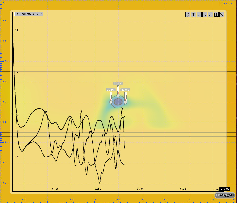
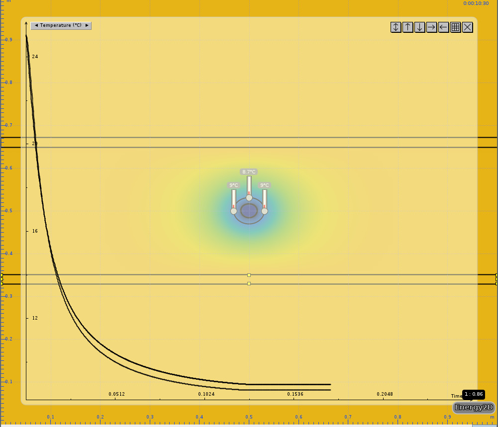
Hello and thank you. I have been using Energy 3D (https://energy.concord.org/energy2d/), which seems to be the result of some research project. Initially, it seemed to work well. But I'm starting to doubt the results from the program, so I'm going to try running a few more rounds with higher time resolution.
What have you considered? The simplifications from EN ISO 12241 or do you have any more professional software for the FEM analysis?
hlph said:
I have looked a little at what Paroc does, they adhere to the standard EN ISO 12241, which describes, among other things, how to calculate heat losses on pipes. It is based on pre-defined expressions for temperature distributions and heat transfer. In addition to temperature boundary conditions, it includes convection and radiation. But this is nothing more than pre-defined solutions to the heat equation, which for arbitrary geometries, for example, can be solved with the finite element method.
I did a quick calculation on a pipe with the data you provided. I let the pipe lie freely in air (nothing enclosing the air), I set temperature boundary conditions on the inner surface and convection on the outer surface. I then found that the temperature went from 2 degrees to 20 degrees on the outer surface of the insulation, which is quite similar to what you get if you use Paroc's calculation program. However, it's not certain that this analysis is realistic for what happens when you have the pipes in an enclosed floor structure.
I have looked a little closer at your recent analyses, both with and without convection. I think the results are a bit strange, but it's probably that I don't quite understand how you've set up the models.
Hello and thank you. I have used Energy 3D ([link]) which seems to be the result of some research project; initially, it seemed to work well. But I am starting to doubt the results from the program; however, I will try to run a few more rounds with higher time resolution.
What have you calculated with? The simplifications from EN ISO 12241, or do you have more professional software for the FEM analysis?
I would have run this as a stationary problem, i.e., no time dependencies. I use a commercial finite element program. If you have done a transient analysis, that explains why some of the curves are so wavy. I wonder how you have modeled the air? Because I interpreted it as you having modeled it in some way and obtained a temperature distribution in the air.
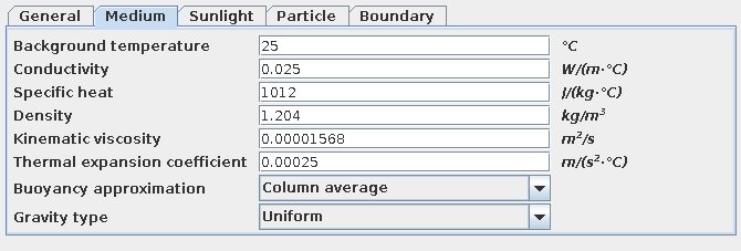
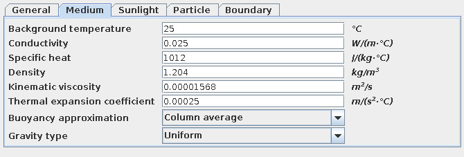
Unclear to me, the program (Energy 2D) had the following preset parameters, double-checked some and it seems to be air.
hlph said:
I would have run this as a steady-state problem, i.e., no time dependencies. I use a commercial finite element program. If you did a transient analysis, it explains why some curves are so wavy. I'm wondering how you have modeled the air? Because I interpreted it as you modeled it in some way and obtained a temperature distribution in the air.
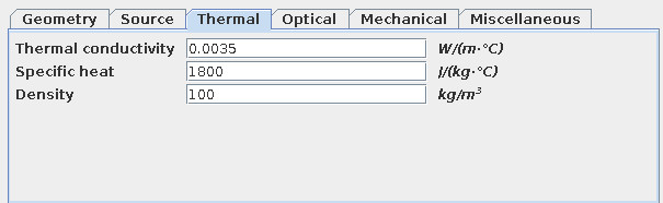
One thing I've done since I posted the images above was to update the heat capacity for the insulation. Initially, I thought that it and the density didn't matter since I was after the values in the steady state. With higher heat capacity, everything became much more stable. Now I have:
hlph said:
I had run this as a stationary problem, i.e., no time dependencies. I use a commercial finite element program. If you've done a transient analysis, that would explain why some curves are so wavy. I'm wondering how you’ve modeled the air? Because I interpret it as you’ve modeled it in some way and gotten a temperature distribution in the air.
Vi vill skicka notiser för ämnen du bevakar och händelser som berör dig.
hlph said:
I won't be able to solve your problems, but I would like to provide some theoretical comments, which hopefully can give a bit more understanding of how it works.frma71 said:

useless said: