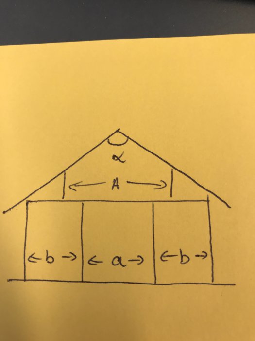
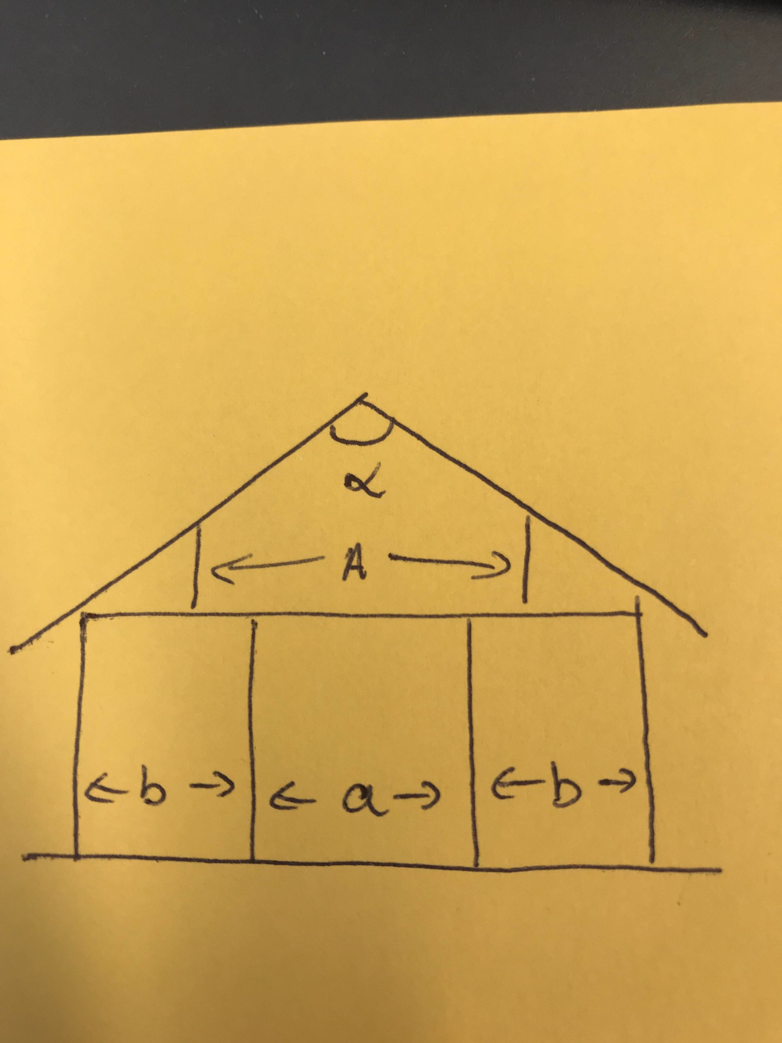
I would need help calculating the distributed load (q) I should use when designing and choosing the method to unload a load-bearing wall. It's a 1 1/2 story villa, but with two load-bearing walls on the ground floor according to the sketch. If I know (q), I can calculate the rest myself since I want to see what different floor plans offer for alternatives in glulam, HEA, etc.
Self-weight of the outer roof 0.65 kN/m2
Self-weight of floor joists: 0.25 kN/m2 (light timber joists)
Snow zone 2
Uncertain about standards and practice when there are two load-bearing walls (+ outer walls)
Is it the load on the attic floor joists you're after? If so, how is the attic used?
Hi,
It is the load on the load-bearing interior walls I'm after. When I know that (q), I can calculate some different suggestions I've sketched for transferring parts of those walls. If it had been a single load-bearing wall on the ground floor, I could calculate (q), but I don't know if there's any specific practice for calculating when you have two load-bearing walls (those with distance "a" between them) according to the sketch (i.e., the load q). The attic is unused and will remain so; there isn't even a floor in the attic. The house was built in '64, and has a plastered brick facade/timber frame on the ground floor and wooden paneling on the half-story.
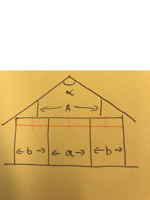
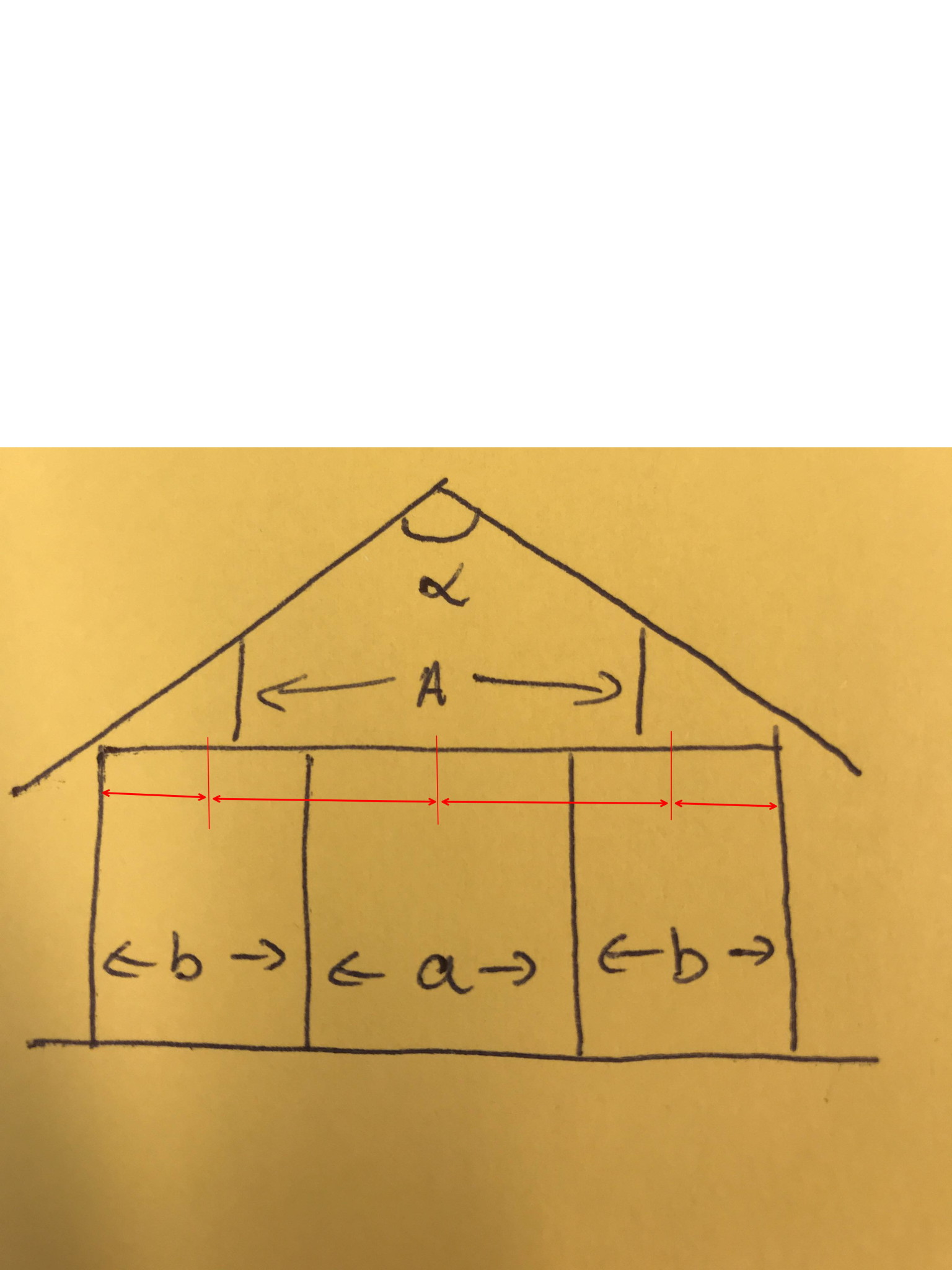
Each floor beam can be considered as a beam with four supports. The total load that the beam represents is distributed on the four supports in accordance with the highlighted section in red.
Simply put, when calculating the distributed load, you assume it is evenly distributed over the four walls even if b<a according to my sketch. For example, if we have a total load from the roof and floor joists of 100 N/m (along the length of the walls), each wall should be considered to support 25 N/m, and consequently, 25 N/m is the dimensioning distributed load, and there's no need to consider that b<a.
Practically, it feels quite natural if you compare it to a "classic" 1 1/2 story house that normally has one load-bearing wall where I instead have two parallel ones (b+a+b = 9m). This means that a potential load dispersal doesn’t necessarily mean I need to go up to 115x630 or something else enormous, even if I'm making quite a large load dispersal.