No, it is a highly practical question. I'm going to install free cooling and wanted to make sure I don't get condensation when the brine pipes are run through the joists.
Yes, I am a control freak and have a hard time trusting people, especially plumbers (due to previous experiences)
Jarlingar said:
Is it a student assignment you've received or a hypothetical question?
15 mm insulation with lambda 0.04 will have an external temperature of approximately +19.5° on the outside and about +3.7° on the inside (towards the pipe). The saturation vapor content for +19.5° corresponds to approximately 73%RH at +25°.
IMPORTANT to choose a diffusion-tight insulation like Armaflex or equivalent.
Thank you very much, but how do you come to that conclusion?
...and what happens if I fill the floor structure with loose fill insulation? (the pipe will run in the middle of the floor structure)
"UPONOR Pipe PLUS with insulation S15 32X3.0 BLUE" is suggested.
/Fredrik
Jarlingar said:
15 mm insulation with lambda 0.04 will have a surface temperature of about +19.5° on the outside and about +3.7° on the inside (towards the pipe).
The saturation humidity for +19.5° corresponds to about 73%RH at +25°
IMPORTANT that you choose a diffusion-tight insulation like Armaflex or equivalent.
Transition resistance is expected, I have studied a lot of moisture.. Moisture expert.
It doesn't matter if you have additional loose-fill insulation around the pipe from a moisture perspective.
With the chosen hose, you can manage, as mentioned, without condensation up to about 73%RH at +25° if the cooling medium is +2°.
Okay, I am grateful for the info and I'm not questioning you, I just want to understand.
Logically, the surface of the pipe should get colder if I add more insulation outside the pipe (with non-diffusion-tight insulation) with the risk of condensation, or does this have to do with the energy required to condense the water vapor (heat of vaporization)?
If you have the energy, please explain how one thinks/calculates or refer to something I can read, I am decent at math and physics in general but not a designer or builder.
Jarlingar said:
You calculate with resistance to heat transfer, I've studied moisture a lot.. Moisture expert.
It doesn't matter if you have additional loose fill around the pipe from a moisture perspective.
With the chosen hose, as stated, you manage without condensation up to about 73% RH at +25° if the cooling medium is +2°
Or say it like this. I have the same pipe, same temperatures. But I have 15mm diffusion-tight insulation and an additional 135mm non-diffusion-tight insulation. For simplicity, the same lambda. We assume a large air flow so that the outside of the outer insulation is 25 degrees.
Then it will be 2 + (25-2)*(15/150) = 4.3 degrees on the surface of the inner insulation? and risk of condensation in the outer insulation?
What am I missing?
Explanation of the calculation above:
Tx = temperature on the surface of the inner insulation.
Tk = cold carrier temp (2 C)
To = ambient temp (25 C)
ti = thickness of inner insulation (15mm)
ty = thickness of outer insulation (135mm)
Tx = Tk + (To-Tk)*(ti/(ti+ty))
/Fredrik
Jarlingar said:
The surface of the pipe will never be colder than the refrigerant.
It is +2° surface temperature on the pipe I have considered.
Hmm, in connection with the cold pipe it will be two degrees, halfway into the insulation (armaflex, loose fill or whatever it may be) it will be between 2 and 25, etc. Or am I thinking completely wrong?
I know that's not actually the case in reality, could it have to do with quadratic expansion? Like all the cold is coming from a small area, while the heat is coming from a large area?
Jarlingar said:
Yes, but it doesn't matter if you have 5 meters of loose fill around the pipe, it will still be +25° in the loose fill.
I won't be able to solve your problems, but I would like to give some theoretical comments, which hopefully can provide a bit more understanding of how it works.
This is a typical stationary heat conduction problem. The heat conduction problem is governed by a differential equation that describes how heat spreads in a body based on the energy we supply. Then, what is needed is a constitutive law that connects the energy flow with a temperature gradient, simplistically a temperature difference. The law usually used is Fourier's law, which states that the energy flow is proportional to the temperature gradient. The proportionality coefficient is the thermal conductivity, lambda, as mentioned earlier in the thread. If we take a simple example, a wall in the same material. Through that wall, there is a certain energy loss, and then the heat conduction equation and Fourier's law will indicate that the temperature varies linearly through the wall's thickness. I've seen the same reasoning in the thread for pipe insulation. The problem is that we don't have such a simple case. We have a pipe and insulation with a circular cross-section. I believe it is easiest to think of looking at the energy flow through a section that looks like a pie slice. The energy that goes in at the innermost point (the surface of the pipe) should be as large as the one that exits at the edge (the outer surface of the insulation). Since the area at the edge is much larger than the area at the tip, the energy flow per unit area will decrease as we move from the surface of the pipe to the outer surface of the insulation. But Fourier's law still applies, meaning the energy flow per unit area is proportional to the temperature gradient. To reconcile this, the temperature must vary non-linearly through the insulation; the temperature gradient will decrease the further out you go. One might ask if it is possible to approximate this with a linear temperature variation. You could do so with a clear conscience if the insulation were thin, but it isn't, so making such an approximation is questionable.
The next thing I read in the thread is discussions about what temperature the insulation will have on its surface. The insulation will not have the same temperature as the surrounding air. The primary reason for the heat transfer between the outer surface of the insulation and the air is convection. It is usually assumed that a convection boundary condition is governed by the energy flow through the surface being proportional to the difference between the surface temperature and the temperature of the surrounding air. The proportionality coefficient is, unfortunately, tricky to determine. It depends on the surface characteristics and definitely on the air velocity. If the air is stationary, you have natural convection. Then the heating of the air at the surface will give rise to movement in the air.
Those were some comments, and they might confuse more, but I still think one should be cautious about overly crude explanatory models and assumptions.
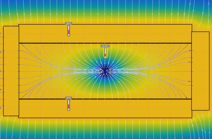
I made a simulation in Energy2D, which is free to use, and created a model. The image shows the simulation when equilibrium is basically reached.
My conclusion is that one should not place brine pipes in insulated/unventilated spaces unless there is a vapor barrier in the outer layers. I really hope I'm wrong :/
The model has four surrounding blocks that maintain a constant temperature of 25 degrees, and then it has a block in the middle with the same properties (lambda, density, and heat capacity) as mineral wool. In the middle, it has a circle that represents the pipe with a fixed temperature of 2 degrees.
Lambda, density, and heat capacity do not affect the equilibrium state at all.
Vi vill skicka notiser för ämnen du bevakar och händelser som berör dig.
")
Jarlingar said: