Hello
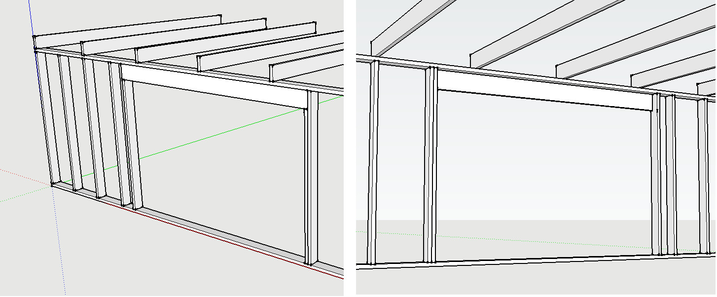
How would you consider the wall plate when dimensioning with respect to point loads from the trusses in the following case?
1. Do you consider the wall plate as freely supported (to be on the safe side)
2. or do you think that the load-bearing beam constitutes a continuous support, even though the beam does not support the entire width of the wall plate?
Hello
How would you consider the top plate in dimensioning with regard to the point forces from the trusses in the case below?
1. Do you consider the top plate as simply supported (to be on the safe side)?
2. Or do you think that the support beam constitutes a continuous support, even though the beam does not support the entire width of the top plate?
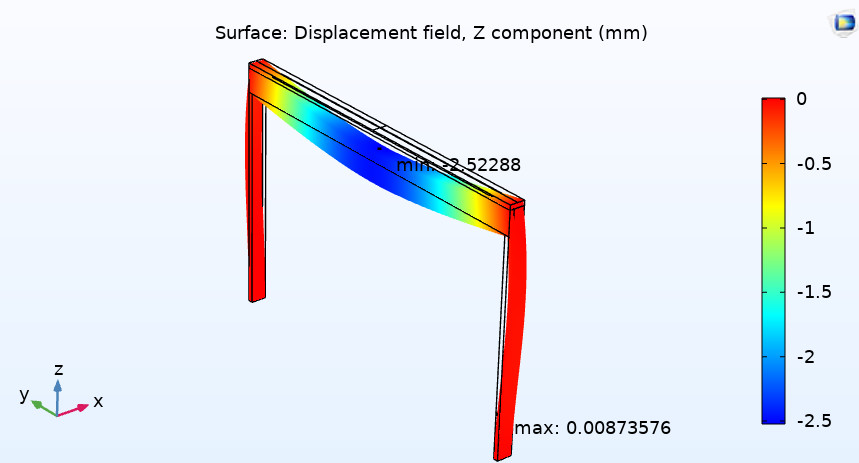
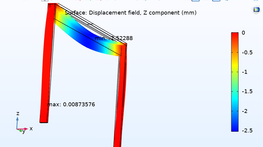
For those interested: I compared a simple case with a point force in the middle where I considered the cross-section as an upside-down L-section that is simply supported between the support columns. Fixed at the bottom and only deflection in the load plane. Did a simulation to confirm the calculation, see image below.
Iz (moment of inertia) becomes 111314214 mm^4, point force of 4 kN, L = 3.33m, E = 11 GPa.
Deflection according to calculation (PL^3/48EI): 2.513 mm
Deflection according to simulation: 2.52 mm.
I now realize in hindsight that it is quite logical to combine the parts into a single cross-section.
Click here to reply
Vi vill skicka notiser för ämnen du bevakar och händelser som berör dig.