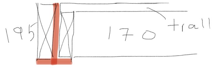
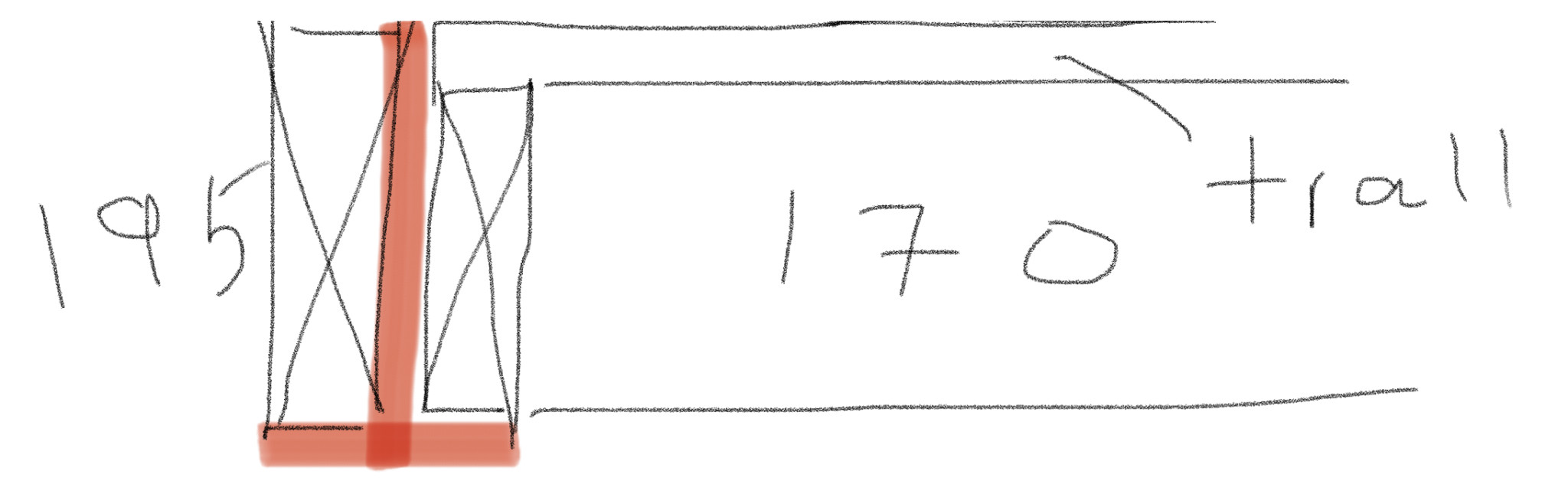
I imagine that a beam of this style would be nice (seen from the short side). For now, I assume that the floor joists in the transverse direction can be solved with 170 mm studs and that one must accept that it will not be super rigid (was it 120 mm in the existing one?)
I envision the beam being made of stainless steel plate, two strips, and a fillet weld on each side. The steel beam becomes quite integrated into the construction and only the edges will be visible. It will be quite pleasant to assemble too, without a lot of wood-metal fastenings.
Regarding dimensions, the goal is a moment of inertia of 1895 cm4 for 15 mm deflection according to previous calculations. If the two wooden joists are properly spliced along the length, they can be accounted for in the stiffness. This reduces the requirement for the steel beam to 1660 cm4 (assuming a 10 GPa E-modulus for wood). The bottom flange can be chosen somewhat freely in width, allowing 45 mm to protrude beneath the outer joist. It can be selected to match some standard for flat iron, but let's say 120 mm. The plate then needs to be 12 mm to achieve the desired deflection. The beam's weight is not included in the example, it is about 250 kg, which increases the deflection to 20 mm.
I think it might be a bit heavy to deal with, but it could be reasonable. The next step is considering whether to camber the beam. If welded, it shouldn't be too difficult, except for needing to cut the beam web with a little curve and then tighten the flange when welding. With such small deflections relative to the span, calculations can be done similarly even if the beam is cambered, with no significant nonlinear effects to consider. Simply subtract the camber from the calculated deflection. So if you camber, for example, 30 mm, the allowable deflection in the calculation becomes 45 mm instead of 15 mm. In the same scenario, you can then reduce the moment of inertia to a third. It uses less material but is more expensive to manufacture. I have no personal feel for that balance; it’s a business case issue
In any case, those were some collected thoughts to add to the idea fire.
I imagine a support beam in this style would be nice (viewed from the short side). For now, I assume that the joist in the transverse direction can be solved with 170 mm studs and one must accept that it won't be super stiff (was it 120 mm in the existing one?)
[image]
I imagine the beam is made of stainless steel plate, two strips, and a fillet weld on each side. The steel beam will be fairly integrated into the construction and only the edges will be visible. It will also be nice to assemble without a lot of wood-metal attachments.
Regarding dimensions, the goal is a moment of inertia of 1895 cm4 for 15 mm deflection according to previous calculations. If the two wood studs are properly spliced along the length, they can be accounted for in the stiffness. This reduces the requirement for the steel beam to 1660 cm4 (assuming a 10 GPa E modulus for wood). The bottom flange can be chosen somewhat freely, allowing 45 mm to protrude under the outer stud. Can be chosen to be a standard flat bar but let's say 120 mm. Then the plate would need to be 12 mm to reach the desired deflection. I haven't accounted for the beam's weight in the example, it is about 250 kg which increases the deflection to 20 mm.
I think it might be a bit cumbersome to deal with, but perhaps it's reasonable. The next step is if the beam is cambered. If it's welded, it shouldn’t be too troublesome other than needing to cut the beam web with a slight curve and then clamp down the flange when it's welded. With such small deflections relative to the span, calculations can be done the same way even if the beam is cambered, with no noticeable non-linear effects to speak of. You simply subtract the camber from the deflection calculated. So if you camber 30 mm, the allowed deflection in the calculation would be 45 mm instead of 15 mm. In the same example, one could reduce the moment of inertia to one-third. It would be less material but more expensive to manufacture. I don't have a feeling for that balance, it's probably an economic question
Those were some collected thoughts to the idea bonfire anyhow.
A stainless "beam" of that type with only a fillet weld on one side will become like a banana and in the wrong direction after it's welded...
Then there's the question of whether you're thinking ferritic or austenitic stainless steel? The E modulus is not the same for them...
Straightening stainless steel is not the same at all as with black steel, so no, not a good idea...
Moreover, the coefficient of thermal expansion in stainless steel means that great consideration must be given to the choice of dimension of the pieces to be welded together, as well as the welding sequence...
I would say that the cost of this solution will be very expensive...
I would consider approaching the problem from a completely different angle. The fact that it wobbles when rolling out is not "really" a problem until it reaches the other side and hits.
If you were to place a small "ramp" in the form of a wedge in the middle, preferably with a series of ball-bearing wheels and a small "wear surface" made of steel or plastic with good wear resistance, it would solve the issue by lifting the cover when it reaches its final position.
The downside is that you get a protruding part in the middle of the short side of the roof.
An alternative would be to have some mechanism at the edge to lift up the roof when it comes. Let's say you have an L-shaped bracket where the lower part of the L sticks under the roof when it reaches. As the roof arrives so that "edge meets edge," the L starts to rotate backward, lifting the roof with the underside of the L and is completely upside down when the roof is at the right height to roll further. The simplest method would be to have two Ls back to back (like a rigid Z or half a swastika) with an axle in the middle. You can then have a motor or similar that rotates it half a turn at the right pace to match the rollout.
To reduce the risk of getting stuck in it at other times, you can either have a cover that folds away or let the entire mechanism slide out when the roof is sent out.
A stainless "beam" of that type with only filet weld on one side will become like a banana and in the wrong direction after it is welded..
The question is whether you are thinking of ferritic or austenitic stainless steel? The modulus of elasticity is not the same for them..
Redirecting stainless steel is not at all the same as with blacksteel, so no, not a good idea..
Additionally, the coefficient of thermal expansion in the stainless steel means that great care must be taken with the choice of dimension of the pieces to be welded together, as well as the welding sequence..
I would say the cost of this solution will be very expensive..
I am not a welder so I don't know how to manufacture such a beam in detail. But I have been involved in the development of lots of welded stainless steel constructions and this design would not be the least bit strange in those contexts, but that's in the industry so maybe different than what a "village smith" has access to.
Austenitic or ferritic makes no difference for the stiffness calculation, the difference in modulus of elasticity is negligible in relation to the accuracy we have in our estimates.
You should have the same or similar dimensions on the web and flange and weld in several passes alternately on both sides.
Not saying it's super easy but not exactly groundbreaking with a T-profile of stainless steel.
I would consider approaching the problem from an entirely different angle. The fact that it sags when it rolls out isn't "actually" a problem until it reaches the other side and hits. If you were to place a small "ramp" in the shape of a wedge in the middle, perhaps with a series of ball bearings and a small "wear surface" made of steel or a plastic with good wear resistance, it would lift the cover up when it approaches its final position.
The downside is that you will have a protruding element in the middle of the short side of the roof.
An alternative would be to have a mechanism at the edge to lift the roof when it comes. Say you have an L-shaped bracket where the lower part of the L sticks under the roof when it reaches the front. As the roof meets the edge, the "edge goes against edge," and the L begins to rotate backward, so the lower part of the L lifts the roof and is completely upside down when the roof is at the right height to roll further. The simplest would be to have two L's back to back (like a rigid Z or a half swastika) with an axle in the middle. Then you can have a motor or similar that rotates it half a turn at the right pace to match the roll-out.
To reduce the risk of getting stuck during other times, you could either have a cover over it that folds away or let the entire mechanism extend when the roof is deployed.
These are good ideas and have already been discussed earlier in the thread with some refinement to have a built-in support wheel at the pool edge that the middle part can roll up on at the end of the motion. But TS seems more eager to increase the rigidity and avoid extra support.
Those are good ideas and they have already been discussed earlier in the thread with some refinement to have a recessed support wheel on the pool edge that the middle section can roll onto at the end of the movement. But TS seems more keen on increasing the rigidity and avoiding extra support.
Yes, that TS has focused on a solution is quite clear, but I am also quite skeptical of the support wheel solution.
(I have actually read the whole thread. )
Yes, that TS has focused on one solution is quite clear, but I'm also quite skeptical of the training wheel solution. (I have actually read the entire thread. )
It's probably good to be open to more solutions. I counted your suggestions into the special support category and thought you might have missed that it had been discussed earlier
Yes, that TS has focused on a solution is quite clear, but I am also quite skeptical about the training wheel solution.
(I have actually read the entire thread. )
The problem, as TS has also pointed out, is that the short side sags, i.e., the side that has a span of over 4 meters. On that line, TS has only used a continuous 45x195.
the problem, as TS has also pointed out, is that the short side sags, meaning the side that spans just over 4 meters. On that section, TS has only used a full-length 45x195.
Good morning! That is probably a misunderstanding. The short sides do not sag. They have 3 wheels supporting them.
It is the middle beam and the open long side that sag.
These are good ideas and they have already been discussed earlier in the thread with some refinement to have a recessed support wheel on the pool edge that the middle section can roll up onto at the end of the movement. But TS seems more eager to increase the stiffness and avoid extra support.
A support wheel that lowers into the decking won't work. It's a cast pool, which would mean I'd have to make alterations to the pool wall.
These are good ideas and they have already been discussed earlier in the thread with some refinement to have a recessed support wheel in the pool edge which the middle part can roll onto at the end of the movement. But the OP seems more eager to increase rigidity and avoid extra support.
We ourselves considered the idea of a "ramp" but abandoned that idea. Partly for aesthetics, but also because children and dogs run around the pool.
Good morning! It's probably a misunderstanding. The short sides do not sag. They have 3 wheels supporting them.
It's the middle beam and the open long side that are sagging.
I think we mean the same thing. A rectangle has two sides. One side is called the long side (at least if the other side is called the short side). In your case, the long side is just over 8 meters and the short side just over 4 meters. The short side sags (visibly) except right at the end where the short side is supported by wheels.
I think we mean the same thing. A rectangle has two sides. One side is called the long side (at least if the other side is called the short side). In your case the long side is just over 8 meters and the short side is just over 4 meters. The short side sags (clearly visible) except right at the end where it has the support of wheels.
You need to redo the short side as well.
No, a rectangle has FOUR sides.
Two short sides and two long sides.
The short sides and one of the long sides do not sag, they are supported underneath.
The last long side sags because it has no support.
")
Bernieberg said:
I imagine a support beam in this style would be nice (viewed from the short side). For now, I assume that the joist in the transverse direction can be solved with 170 mm studs and one must accept that it won't be super stiff (was it 120 mm in the existing one?)Violina said:
A stainless "beam" of that type with only filet weld on one side will become like a banana and in the wrong direction after it is welded..Dowser4711 said:
I would consider approaching the problem from an entirely different angle. The fact that it sags when it rolls out isn't "actually" a problem until it reaches the other side and hits. If you were to place a small "ramp" in the shape of a wedge in the middle, perhaps with a series of ball bearings and a small "wear surface" made of steel or a plastic with good wear resistance, it would lift the cover up when it approaches its final position.Huggedugge1 said: