6,444 views ·
23 replies
6k views
23 replies
Reinforcement, composite steel decking, construction drawing
Going to build an extension and soon the pouring of the foundation slab will begin, followed by the lecablock walls. The third step is the concrete floor slab. I want to understand what the structural engineer means, preferably over the weekend ")
The composite sheet at the bottom and inserted into the UPE180 beam on the lower side. This is because I have window arches all the way up to the ceiling. The composite sheet is anchored with 10 mm bent reinforcement bars down into the U-blocks and cast in place with fine cement.
Top reinforcement with 6150 is probably about 20-30 mm down in the 180 mm slab? It stands on spacers... Do you lay the underfloor heating pipes over the 6150 or hang them on the underside under the mesh? Seen different pictures...
What I don't understand is the 2 pcs of 10 mm bars that run across the direction of the slab and along the slab. It says 2 pcs 10mm per block. Is this some form of distribution reinforcement? Is this laid directly on the composite sheet loosely and just tied? Why not use, for example, 8150 instead?
Very lost in the reinforcement jungle as there aren't many pictures or good descriptions
Best regards, Joakim

The way I interpret it, it's 10 mm both lengthwise and 10 mm across the direction, i.e. a "mesh"? Tie wire at the cross, I assume? So why not a proper mesh instead? Am I missing something?Matti_75 said:
By the way, is it possible to reinforce too much? So that the concrete cracks more easily or something like that?
Best regards, Joakim
Hmm, sorry for stupid questions, but:
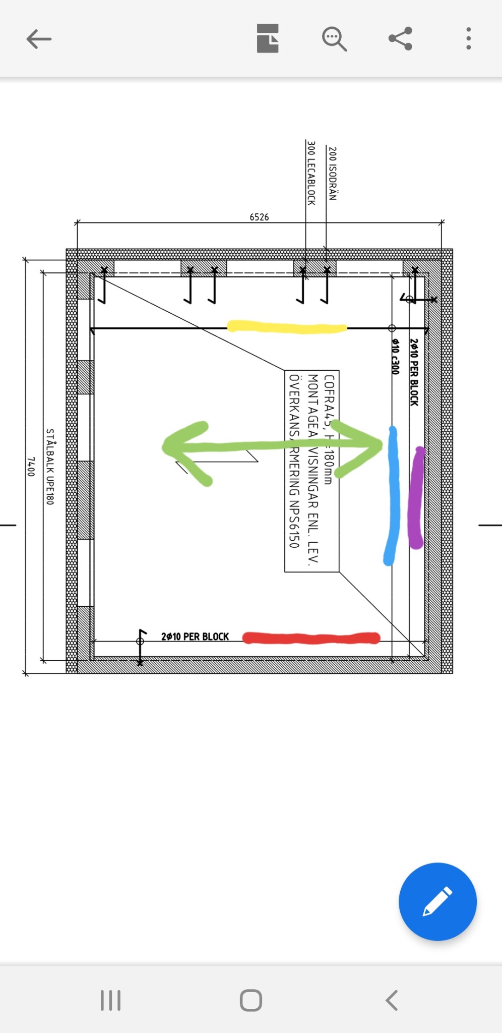
1. Green line shows the plate's longitudinal direction.
2. Red line states 2*10 mm per block, but it’s in the same longitudinal direction as the plate. If you lay these over the entire surface, these bars would either end up in the trough or on the crest.
3. Yellow line same as number 2.
4. Blue and purple across the plates and here I can understand the reinforcement so you get the stiffness between the plates, as you can place the reinforcement directly on the plate’s "crests".
I feel incredibly slow right now but would like to understand for the future
Best regards, Joakim
JoakimSwe said:Hmm excuse the dumb questions, but:
1. Green line is the length direction of the plate. No this shows the laying direction of the bottom reinforcement.
2. The red line states 2*10 mm per block, but is thus in the same length direction as the plate. If you were to lay these over the entire surface, these bars would end up either down in the valley or on the wave top. These are anchoring bars meant to go down into the wall blocks, 2 bars per wall block. Looks like b-bars (bars bent at a 90-degree angle.)
3. Yellow line same as number 2. No, these are the bottom bars.
4. Blue and purple across the plates, here I can understand the reinforcement so you gain stiffness between the plates, as you can lay the reinforcement directly on the "wave tops" of the plate. Purple and red are number 2. Blue shows the distance over which the bottom reinforcement should be laid, i.e., the entire length of the house.
I feel incredibly slow right now but would like to understand for the future
Cheers, Joakim
There seem to be some misunderstandings here. What is marked in green is the direction of the main reinforcement. It doesn't affect the bottom reinforcement (UK) at all since it just lies in the right direction, only the top reinforcement (ÖK).
Based on the principle "Underst i underkant och överst i överkant."
Then the bottom reinforcement (UK) on the drawing is depicted as top reinforcement, so one wonders what kind of person drew this.
Based on the principle "Underst i underkant och överst i överkant."
Then the bottom reinforcement (UK) on the drawing is depicted as top reinforcement, so one wonders what kind of person drew this.
Now it's even more confusing, but I'll call the designer on Monday. Would have liked to understand the principle, but it doesn't seem to be happening.C C.Lundin said:There seem to be some misunderstandings here. What is marked in green is the direction of the main reinforcement. It doesn't affect the bottom reinforcement (BR) at all since it only lies in the correct direction, only the top reinforcement (TR).
Based on the principle "Bottom in the bottom and top in the top."
Then the BR on the drawing is depicted as top reinforcement, so one wonders what kind of person drew this.
The green arrow is how the plates run (from right to left, that is), so I didn't understand why the reinforcement should run along them. But oh well.
The drawing leaves much to be desired in terms of clarity. 2 rebar per block are drawn as B-stirrups that go down into the Lecawall, but the text is incorrectly written. It should have said 2ø10 -B.
Should the slab only be 180 mm? Or is it in addition to the combiplate at the bottom? 180 is definitely far too thin for a 6.5 m span.
Should the slab only be 180 mm? Or is it in addition to the combiplate at the bottom? 180 is definitely far too thin for a 6.5 m span.
Hmm, the clear span is 5.926 m (the total width of the Lecawalls is 0.6 m). PEVA45 with 180 mm handles 6 m?W witten said:The drawing leaves much to be desired in terms of clarity. 2 reinforcement bars per block are drawn as B-stirrups going down into the Lecawalls, but the text is written incorrectly. It should have said 2ø10 -B.
Should the slab only be 180 mm? Or is that in addition to the combiplate at the bottom? 180 is definitely way too thin for a 6.5 m span.
Then there's this mystery with UK that I never seem to understand. Is there a picture somewhere?
Best regards, Jocke
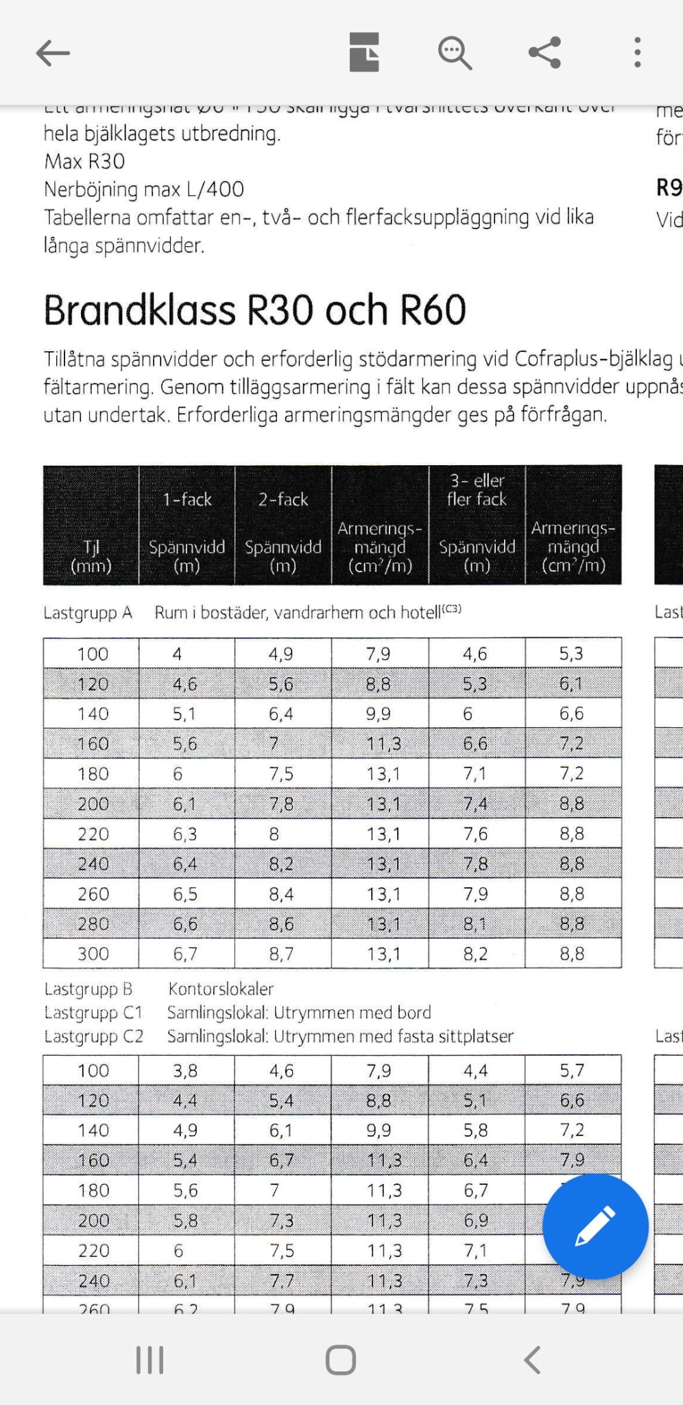
Also looking at Plannja's Combideck which handles 5.9 m without lower reinforcement and with C25/30.W witten said:
I will get C35/C45.
But still there's confusion with the lower reinforcement that I don't understand, so I need to contact the engineer and ask him to clarify.
If it's like a mesh in the lower reinforcement, I understand. If it should lie directly against the sheet metal and be tied in the cross sections, I understand. If it's CC300, I understand.
Otherwise, I'm confused. But why bother with rebar when a mesh should work remains a question, if it's both longitudinal and transverse rebar in the lower reinforcement...
JoakimSwe said:Also looking at Plannja's Combideck which handles 5.9 m without UK and with C25/30.
I will get C35/C45.
But still, there's confusion with UK that I don't understand, so I'll contact the designer and ask him to clarify.
If it's similar to a net in UK, I understand. If it's supposed to lie directly on the sheet and be tied in the crosses, I understand. If it's CC300, I understand.
Otherwise, I'm confused. But why use reinforcing bars when a net should work remains the question, if it's both longitudinal and transverse bars in UK reinforcement...

Here is how I think the UK should look, hanging 10 mm in each valley in the sheet (i.e., longitudinal direction, green, red, and yellow) but only 1 piece in each valley/1 piece/300 mm. Then, to support these, an additional 10 mm lies directly on the sheet, 300 mm in the blue and purple direction. Like a net where all the crosses are tied together. Then the curved L's come up from the masonry blocks, 2 per block, and are tied together with ÖK or UK?
https://www.byggahus.se/forum/attachments/oek_1_bock-jpg.45947/
https://www.byggahus.se/forum/attachments/oek_1_bock-jpg.45947/