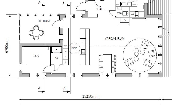
I'm sketching the foundation for our vacation home. The house, which is a single story with a 22-degree gable roof, will stand on pillars on rock. It is 15 meters long and 6.5 meters wide and will stand on three rows of pillars. What I'm wondering about is if it's possible to retract one row of pillars so that the house projects out a bit. Preferably about 80 cm but anything over 20 cm would be good. So, for example, one row of pillars as usual along the long side. One row of pillars in the middle of the house and the last one, for example, 6 meters from the first. I'm thinking preferably of a joist with C24 220x45 cc 600.
It is absolutely possible to pull in one of the foundation lines. It becomes a bit trickier to calculate, but not a formal problem. With the spans that become relevant, 45x220 c/c600 C 24 must suffice.
Sounds like there is hope
On 2/3 of the house's length, there is no load-bearing inner wall (open to the ridge). I assume that complicates the desire to extend the joist? Could it be appropriate to have double 220x45 for example about 2 m over the recessed plinth row and out towards the protruding outer wall? Or are there other suitable measures?
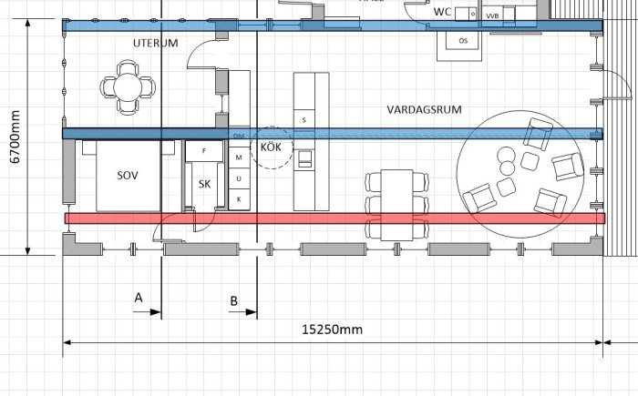
Approximate placement of foundation rows marked in the plan drawing below. Indented foundation row marked in red. The reason I want to indent the row is primarily aesthetic. The foundations in the row along the lower long side are about 1.6 meters high on the far left and 3 meters on the far right if they are flush with the outer wall. They can on average be made perhaps 5 cm shorter for every 10 cm I indent the row.
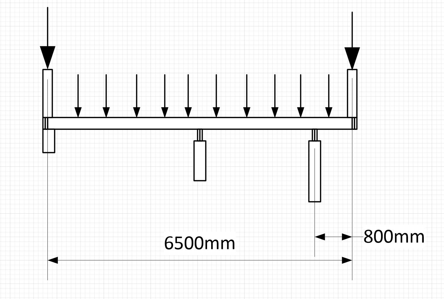
My attempt to sketch a section and loads. However, I'm not sure what values for the loads are reasonable. It should be the section that opens to the ridge that is the most challenging?
You should not expect quick reactions. It is actually quite a complex situation with several possible solutions. One issue is the number of plinths and the dimensions of the bearing beams. Another is the size of the floor joists. Additionally, I think one should also consider the aesthetic aspects, especially when it comes to the recessed plinth row. I have been pondering the "question" since this morning and might be able to respond early in the evening.
Another thought: Is the house located in a weather-exposed area? Mainly, I'm thinking about the wind.
Fairly exposed to winds but nothing extreme. I would imagine that 20% of the houses in this country are in worse conditions. I do want a substantial roof overhang (60 cm) which might make things worse. The number of plinths is flexible. I was considering a plinth distance of 1.5 meters (?).
Looking at the length of the overhang and relating it to the current loads and an imagined dimension of the floor joists (45x220 C 24), it is just on the edge of acceptable deflection. Reducing the overhang to 700 mm would not be a bad idea.
Now to the question of pillars and beams. You can choose many different models. My calculation is based on you using the same glulam dimension for all beams and instead varying the pillar distance slightly. It usually makes leveling and setting heights easier. I have also aimed to keep the glulam dimension down so that they can be lifted by hand. The loads are lowest in the middle row, so there you can go up to 4 m pillar distance, otherwise 3 m. Glulam dimension 90x270. I have calculated a distributed load in the middle row of 7.6 kN/m, 18 kN/m in the outer row (at the overhang), and 17 kN/m in the inner row.
Regarding the choice of material for the pillars, I think you should choose glulam for the outer row where they are quite long. A 90x90 dimension is sufficient. Even if they are partially hidden by the overhang, it still looks the most stylish.
I haven't taken the angled structure into account since it doesn't appear fully on the drawings. Probably an extra pillar is needed under the inner beam opposite this.
bossespecial: Would you like to check my calculations? There are many numbers, so it's easy to make a mistake.
Ok. Thanks. I'll take the advice and reduce to a 700 mm overhang. I was considering using double 45x220 beams but realize that a glulam beam would lead to fewer piles, which would be good. Any other reasons for using glulam in the beams? For the piles, I was previously considering cast piles. But casting three-meter high piles is quite cumbersome, even if there are only a few that are that high. A glulam post is undeniably more convenient. A friend might possibly help me with manufacturing steel pillars, which is an alternative. Aesthetically, the plan is to cover the foundation with today's typical horizontal wooden slats, so you won't see much of the piles.
In my experience, the surface of glulam copes with the outdoor environment somewhat better than regular construction timber. I think it would be a shame to miss such a clear design opportunity by covering the foundation posts. Instead, highlight them. Possibly place something behind the outer row of posts!
The building needs to be stabilized in the horizontal plane. The simplest way to do this is by using sheet material on or under the floor joists and anchoring it to the ground at some point. Alternatively, you can place diagonal braces in suitable locations. Post houses are not automatically stable.
I guess I should/must take this to a constructor? It's not clearly described on the municipality's website what requirements there are, but it seems documentation is needed for the technical consultation. Any tips on how/where I can get help with that?
Of course, it's also nice to feel confident in the solution myself (I mean, I'm not doing it just for the municipality's sake.)
Vi vill skicka notiser för ämnen du bevakar och händelser som berör dig.

")