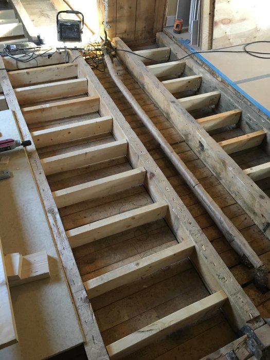
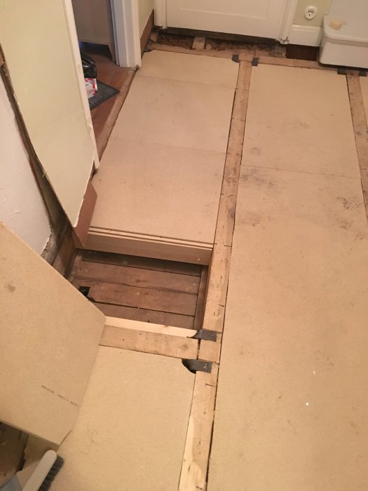
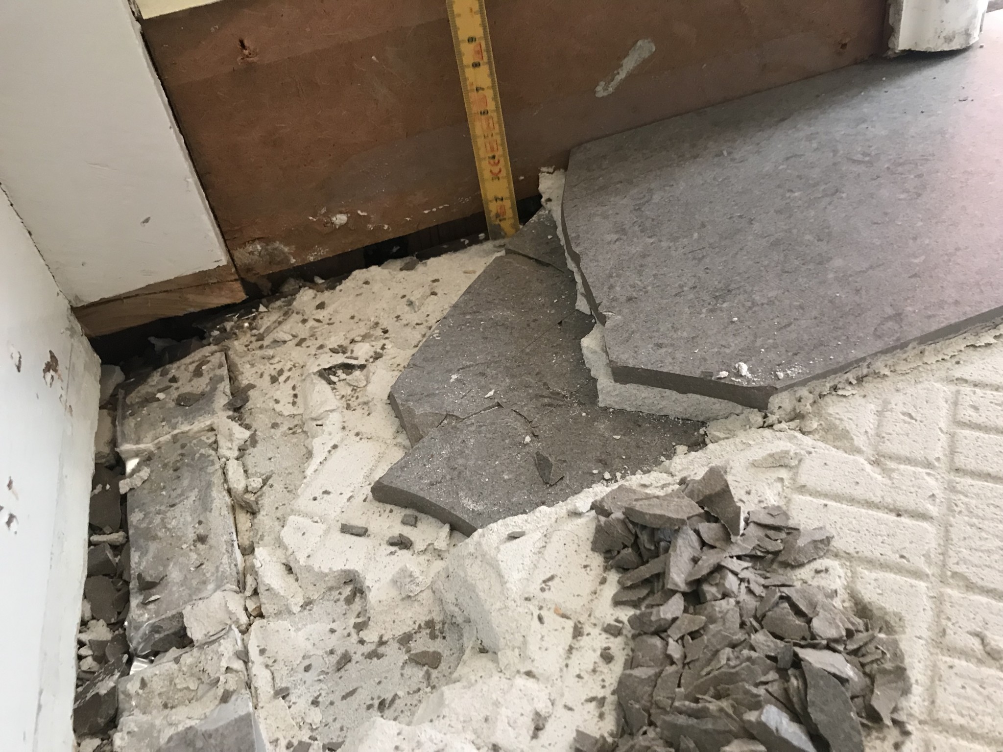
We have begun tearing out a relatively newly laid tile floor due to significant concerns about the execution since some tiles have started to come loose. The original plan, according to the craftsman himself and the agreement, was to supplement the joist frame to cc 300, which today is between cc 600 and cc 700, then lay grooved board, reinforcement, leveling compound, and then tiles with 30x60 tiles. The maximum span of the joist is 4.2m (2x50x180 offset by 20mm in height from the 1950s) and the total continuous area is about 25sqm.
Are we strange to think that the method change below feels questionable?
Their method
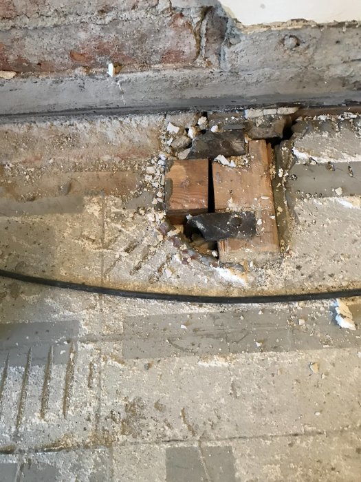
- Blocking lowered ~22mm in each bay, 45x120 on cc 300 which has been screwed to the existing framework with gaps in many places(?).
- On these blocks, flooring chipboard has been placed, lowered between the joists.
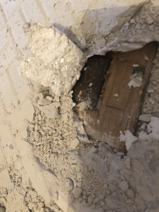
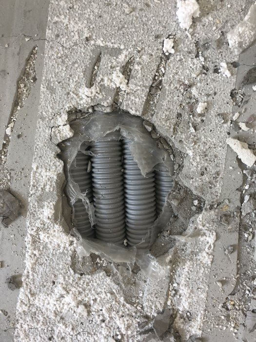
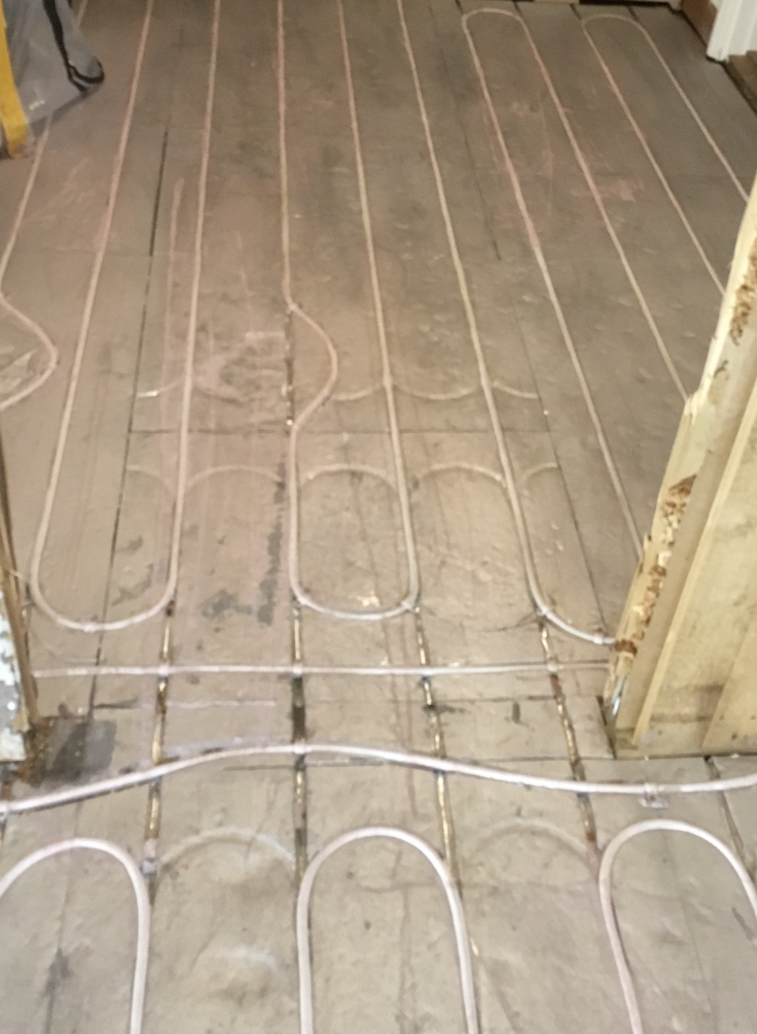
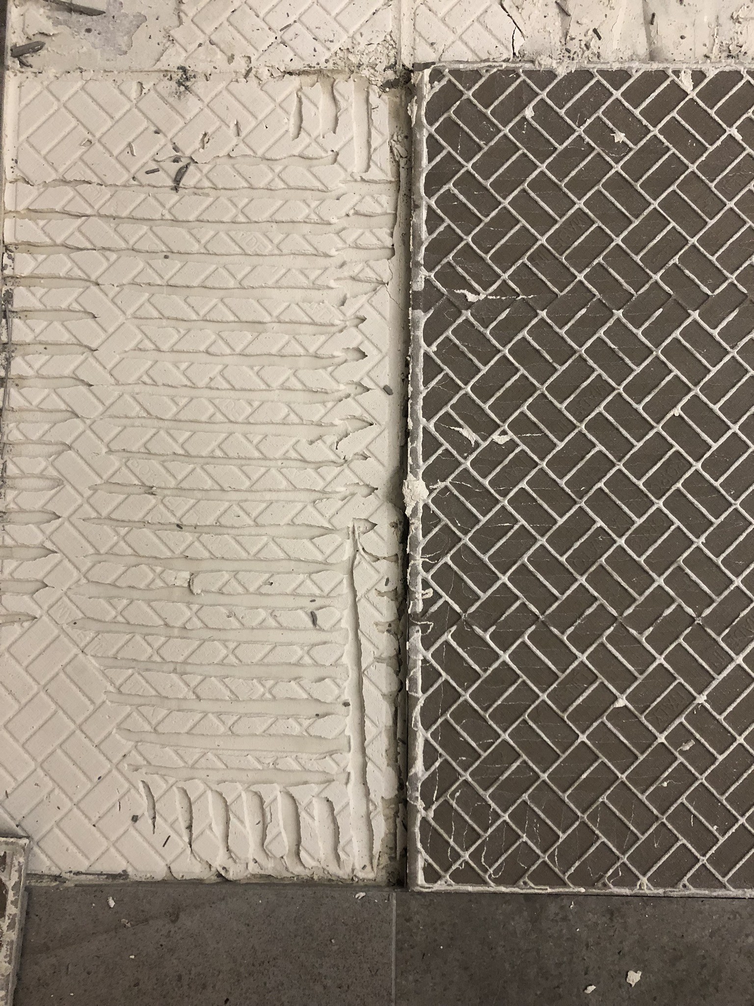
- Then a Flooré board (Aluminum-clad EPS) was mounted with LIP thinset. They have also carved out EPS from the boards for old transitions (where the hose takes an extra bend in the first picture below). The surface leveling of the thinset seems to have been poor in some of the places we've checked.
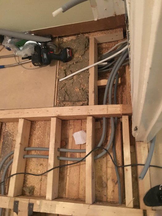
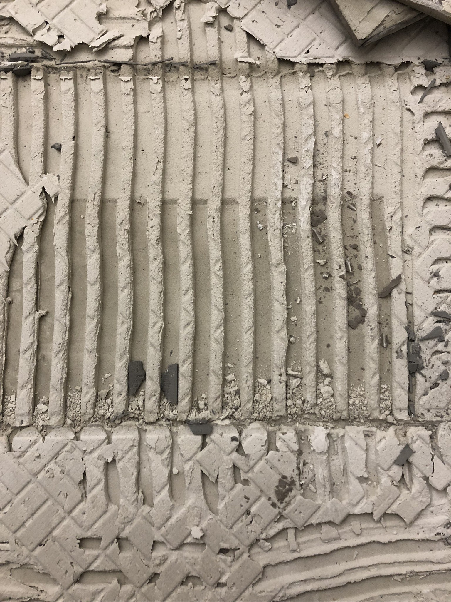
- The Flooré board had been laid directly on PEX water pipes. The hoses pass over a steel beam here.
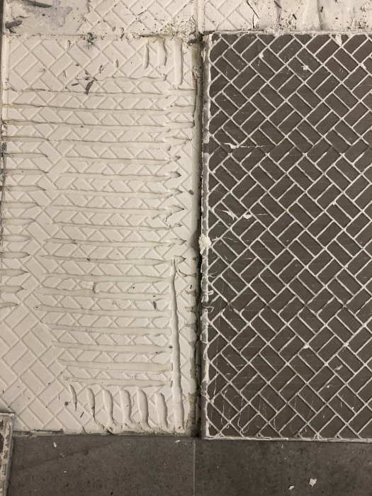
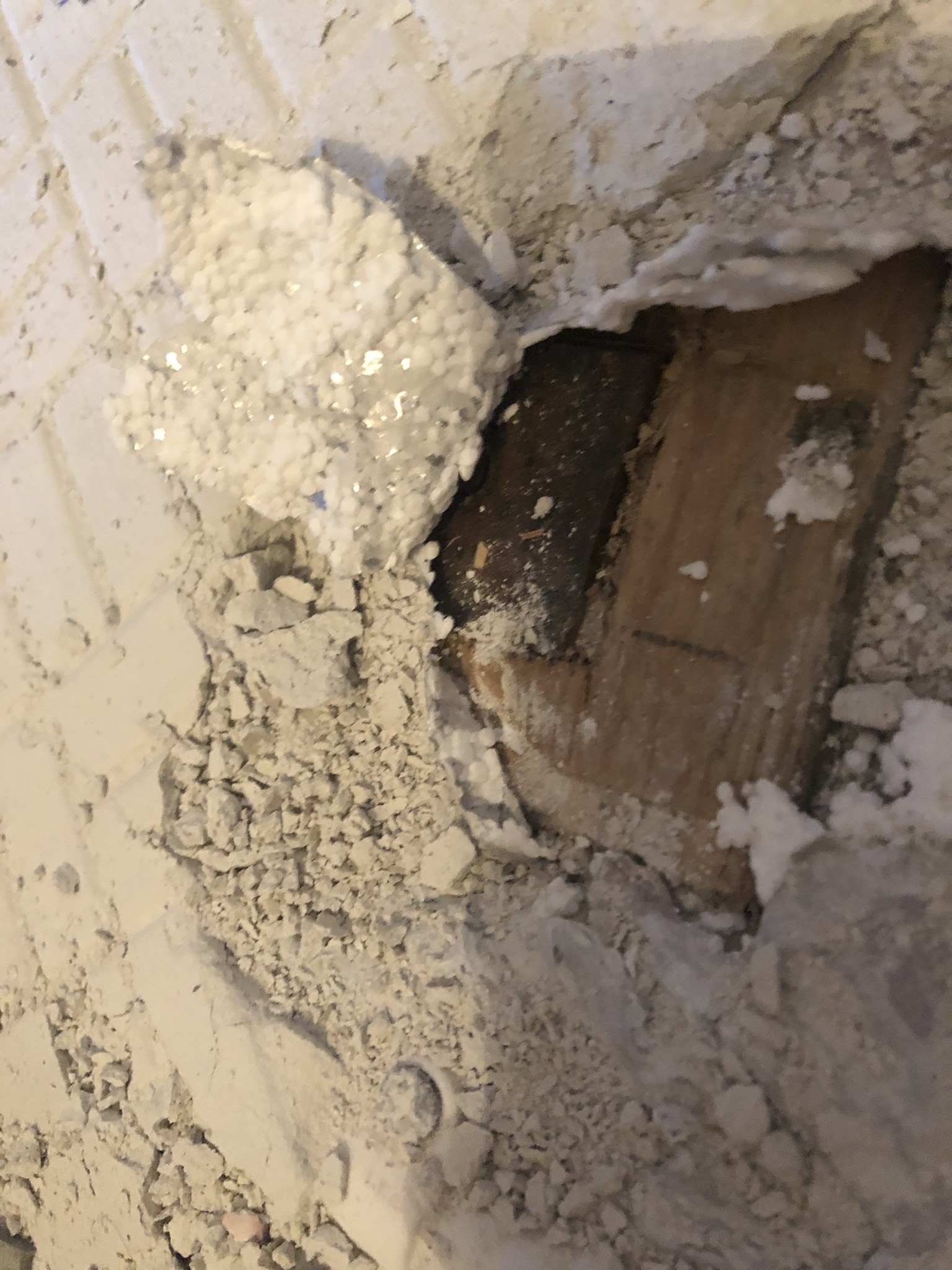
- Directly on these boards, tiles have been laid with LIP Multifix light. Tiles have been double-stacked in some places, and the adhesive has been applied very unevenly. The tiles we lifted came off, we believe, very easily and have been very clean on the back when removed.
Firstly, it seems spontaneously like there is a lack of a layer of levelling compound over your Flooré boards. It doesn't seem like these can be the sole substrate for tiles.
Secondly, it seems like regardless of this, it is alarming if loose tiles have poor coverage underneath. It makes one wonder if the adhesive skinned over during installation.
It should be possible to lay tiles directly on the boards. Leveling is only needed in bathrooms to create a slope. The adhesive has clearly skinned over before the tiles were set. Very clumsy.
I did my hallway in a similar way 15 years ago. Recessed chipboard between cc60 joists. I reinforced the chipboard with 45*45 battens on the back to increase bending resistance.
Complementary regarding fix on sheet metal...
LK has its eps16 system, where you can place tiles directly on the aluminium sheet. In their description, a covering layer of primer is included between the sheet and the fix. This is likely needed for the adhesion of the fix and corrosion protection of the aluminium sheet. Otherwise, I don't see any issues with the methods and execution of the work. The joist will be sufficiently rigid. Except that the fix has skinned over before tile setting. They were in a hurry and careless. Really unfortunate
The method to stabilize the floor structure is based on a misconception, that the lack of stiffness in the floor joists can be fully compensated with gussets. 100x180 mm is too weak a dimension for a span of 4.2 m. In this case, the deflection becomes too large and it doesn't help what material you use at the top. If chipboard is to have any positive effect on the deflection, it should be glued and screwed on top of the floor joists. The best solution is to insert glulam beams between the existing ones at a slightly higher height so that they take over the load-bearing. Suggestion: 140x225 mm. If it is important to keep the floor structure's height down, you can use 165x180 mm instead.
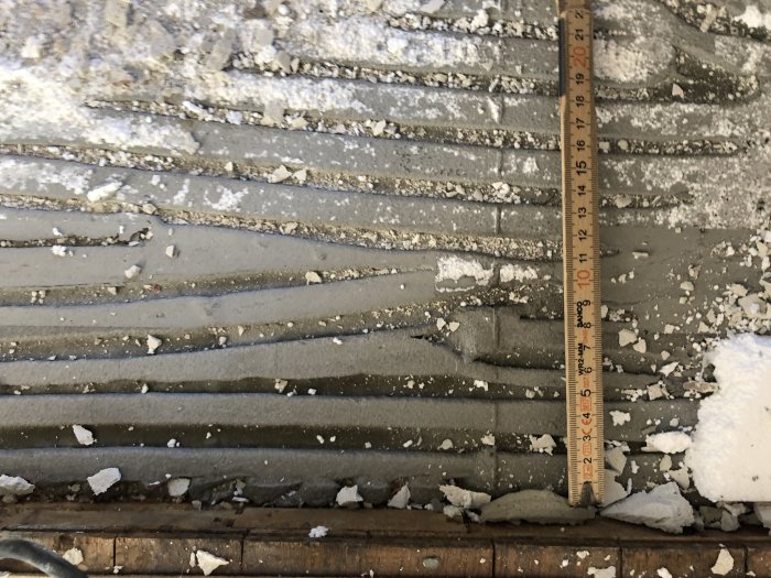
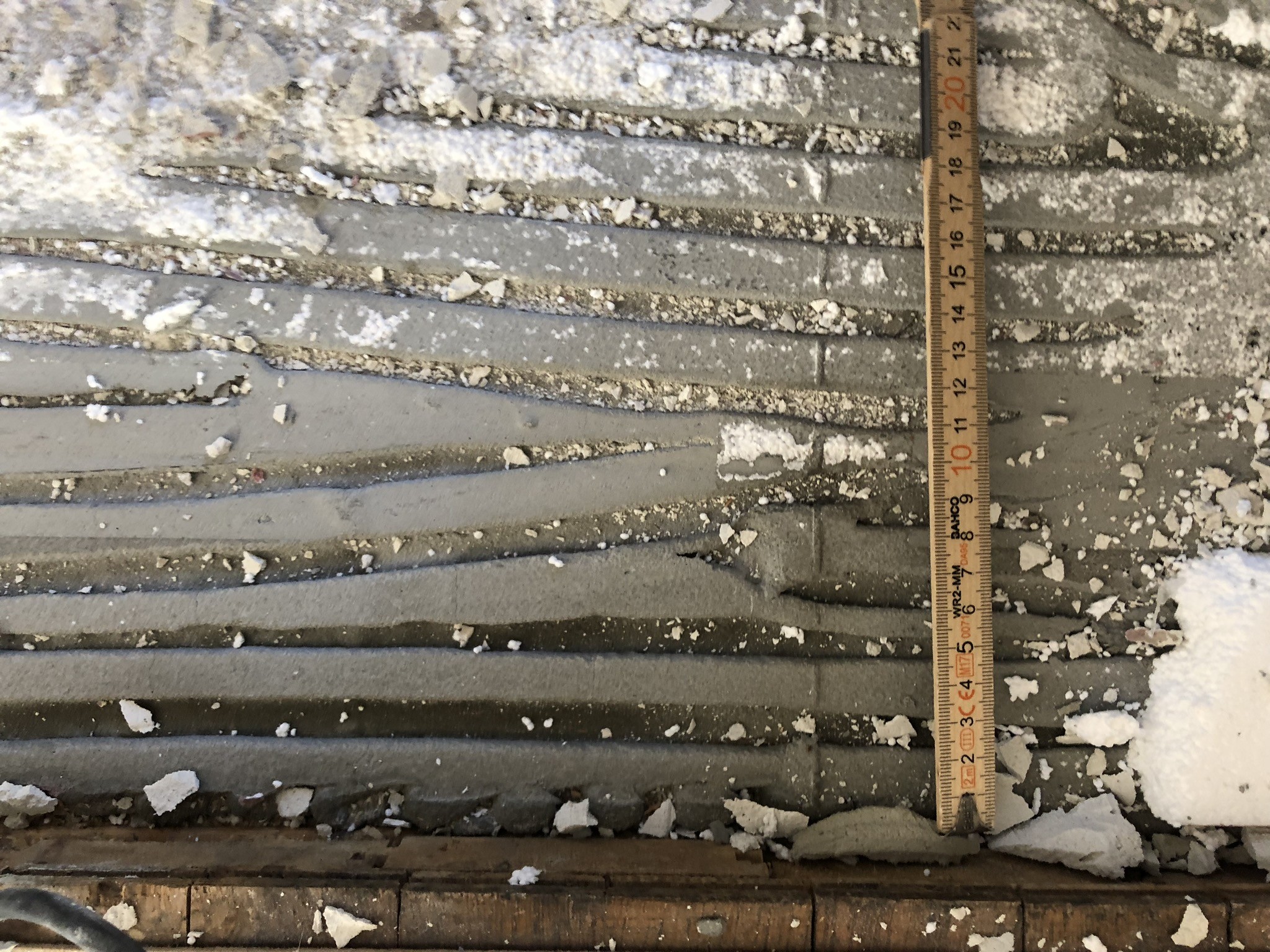
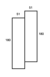
In a part of the floor structure, there are two floor joists joined together, offset in height by 20mm as shown in the image below. Can these be recalculated to what it would correspond to if it were only one joist? Because I assume it's neither like a 51x180 nor a 102x200?
Then we've received three construction statements (attached) which we find highly questionable with strange results and odd conclusions about protected zones in the floor structure, mandatory ways to perform the work, and that calculated loads are rarely occurring. (The floor is now modified with cc300, chipboard flooring, and leveling compound)
Attached files
- Statement 1
- Statement 2 after we provided additional information
- Statement 3 after it changed values to incorrect basic conditions. E.g., incorrectly moved the position of steel beam from statement 2 and increased dimensions.
How do you calculate deflection for two joists as shown in the image below, they have a total height of 200 together? For I assume it will neither be like a 51x180 nor a 102x200?
I have looked at the statement a bit and they are somewhat lacking/brief. For example, it is not clear against which loads it is checked, no reference (chapter, section) to where the deflection requirements are stated.
Also, comparing with SBN I do not consider correct when it comes to serviceability limit controls as in your case. It is also not clear which load combinations in the serviceability limit according to EKS are used. In the ultimate limit state, however, a comparison with the standard used when the house was built is more relevant. I also can't reconcile the dimensions, it doesn't seem to match what you write, has he recalculated the cross-section? Then there is a bit of text that does not add but raises questions, for example, the particle board interacts with the noggings... and what would this contribute with as it does not significantly affect the stiffness in the relevant stiffness direction?
No, we do not understand either and have never, despite requests, received any loads or an explanation of why they are using SBN80 when the house was built in the 1930s and EKS should be used. And the texts in report 2 we just find to be something to confuse..
They have never measured what the cross-section/spans are but have fabricated values based on what they think/want it to be. Initially, they wrote 2x50x200 then they changed it to 2x63x200 in report 3. We have measured the beams to the dimensions shown in the image in my post above 2x51x180 which are offset in height by 20mm.
For example
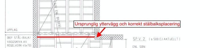
To get 4m, they measured the free space in a room in the basement under the floor structure, between the outer wall and an inner wall. On the other side of the inner wall, there is a steel beam on which the floor structure is laid, where the outer wall was originally (extended in 1951), where we have measured the span to 4.2m.
Have you had a requirement not to exceed a certain height?
As Justus writes, the floorboards should be glued to each other in the tongue and groove to be correct...
One should at least have glued a 13mm floor gypsum board over everything or glued and screwed the entire 22mm chipboard over everything.
Joist cassettes or spars with underfloor heating between existing floor joists, 22 chipboard and glued floor gypsum or at least 13mm leveling compound on the chipboard floor, then it would have worked.
Have you had a requirement not to exceed a certain height?
As justus writes, the floorboards should be glued together in the joints for it to be done correctly...
You should at least have glued a 13mm floor gypsum board over everything or glued and screwed an entire 22mm floor chipboard over everything.
Beam cassettes or battens with floor heating between existing floor joists, 22 chipboard and glued floor gypsum or at least 13mm self-leveling compound on the chipboard floor, then it would have worked
There was a request for as low a threshold as possible against an adjacent surface. But today it has been redone with a floor framework at cc300, grooved floor chipboard on the framework and self-leveled according to the rules and no threshold, without becoming significantly more expensive.
Bbossespecial said:
I assume the statement is ordered by the contractor? The quality of the statement, as mentioned, is very vague and doesn't really say much.
Yes exactly, it is ordered by the contractor because they want to show that the entire job is professionally executed and correct. It fails even in that the tiles were laid the way they were...
Click here to reply
Vi vill skicka notiser för ämnen du bevakar och händelser som berör dig.


nino said:
Have you had a requirement not to exceed a certain height?