The top beam probably needs to stay, can I bolt, for example, a 45x220 on each side of the beam resting on posts at each end?
The span is about 4.7 meters.
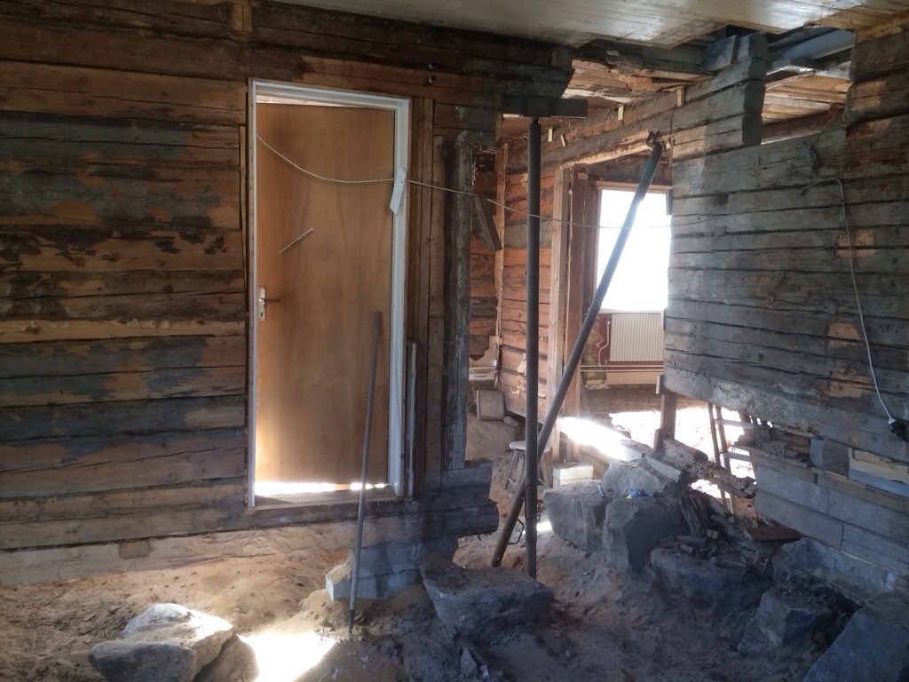
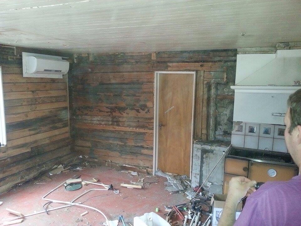
The fireplace has now been removed where the beam previously ended and is supported by standing beams to the right of the door.
The new intended planks will thus be about 1 meter longer...
One must consider that all walls in a log house are load-bearing. Additionally, interior walls help hold the house together.
It's not entirely made of logs from before either, because of the chimney. But it's good to think about stability in that direction as well (and not just the weight from above).
Someone else can probably answer how it should be done.
Yes, exactly, I even think it will be more stable regarding side loads with my new "wall/beam" than before since I will connect it with the wall to the right that isn't visible.
As you can see at the top, there are two blocks embedded in the top beam, on these lie logs that go from outer wall to outer wall, and these are full lengths, not spliced as far as I could see (I have previously torn up the floor on the upper floor). There's also another block at the far right behind the plaster that you can't see, and there is also a block with an overlying log on it.
The wall doesn't continue on the upper floor; there's flooring above this wall/beam.
It must become incredibly strong if you drive French screws through a 45x220 every 30 cm or so.
If we imagine only 2 standing 45x220 bolted together side by side, how much can it support? Can someone calculate this kind of thing on the forum?
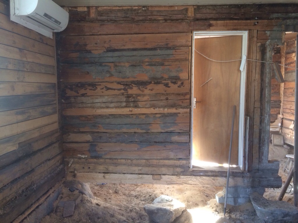
I will upload a better picture tonight where the wall is gone
What is on top?
What will the wall carry?
How is the floor constructed on the upper floor?
Do the floor joists run across or along the house?
Is it a 2-story or 1 & 1/2-story house?
Instinctively, I think that 2 x 45x220 will be more than sufficient.
The wall helps to brace the house (the outer wall) so it must also be compensated.
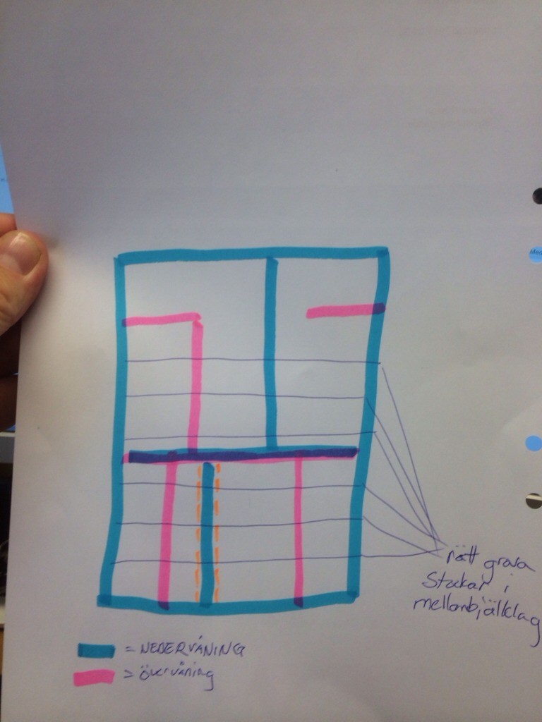
here comes a masterful drawing
blue = ground floor
red = upstairs
orange dotted = current wall
above the wall is the bedroom.
In the floor space are large beams running across the entire house, which I have also drawn (quite large beams in the floor space, if someone can't read my handwriting ), they rest on the blocks visible in the pictures near the ceiling. at about 100-120 cm distance
I don't know what the wall is supposed to support since I'm not sure how much the "floor space beams" rest on the interior wall.
the floor in the bedroom is constructed so that on the "floor beams" I've put back the old wooden planks 35x70 as sparse paneling and have laid underfloor heating pipes between.
the floor beams, or "floor space beams" as I've called them, run across the house, extending from long side to long side without being spliced as far as I can see anyway.
I think the house is a 2-story, there is some sloped ceiling on the upper floor.
I understand that the wall braces the gable, so I was planning to save a plank width there, say 220, and bolt it as 2 posts with 1 bolt in each remaining log stump. on top of this post will then rest either the plank or the laminated beam, whichever it will be
Okay.
How wide is the house?
What is the free span of the beam (that replaces the wall)?
How thick are the joists of the floor structure?
Do you want the joists of the floor structure visible in the ceiling on the ground floor?
Ok.
How wide is the house?
What is the length of the free span of the beam (that replaces the wall)?
How thick are the floor joists?
Will the floor joists be visible in the ceiling of the ground floor?
The house is about 8.5 meters wide.
The distance from wall to wall where the beam/plank will be placed is 4.7 meters.
The floor joists are about 20-25 cm thick and will NOT be visible, the ceiling that shows will remain as the insulation is on it.
Oh, that was long (wide). Are the beams of the intermediate floor that long without joints? Hmm, it means somewhat larger loads with such long lengths (both beam and intermediate floor beams). Try to maximize the width of the supporting posts to minimize the free span. Every centimeter counts.
These are slightly larger spans than I've encountered, so I can unfortunately only speculate. Still, I think 2x220 isn't bad, but perhaps even go up to 3x220? Maybe even 4x220 if the timber logs are that thick...? (Aesthetically speaking, I think the thicker dimensioning fits better with an old house than the modern style with tall narrow studs, and it also gives an impressive look. If you want, you can, according to old customs, clad the studs at the bottom with a 21x95/120/145/170/195.)
As a comparison, (for what it's worth), my garage & workshop is 6 x 11 m. 1 & 1/2 stories with a hayloft upstairs. We've had up to about 4.5 tons of hay there. The intermediate floor is 50x175, 60 cm center-to-center, full 6 m long studs from wall to wall. In the middle along the house, supporting the intermediate floor studs, runs a 100x200 beam supported on the cross wall in the middle, which means approximately a 5.5m free span.
bump, even others than oldboy can respond, I appreciate all answers and thoughts!
Yes, it would be good as I can't really answer, but more discuss, suggest, and speculate. TS needs someone with more experience in this kind of thing, or someone who can do dimension calculation.
the top log should remain, but it might become a bit weaker since you are removing all the logs underneath.
but if you bolt a 45x220 on each side of the log, you should be able to consider this as "a unit" consisting of 1 log and 2 45x220s, this should hold for enormous forces and be practically impossible to break.
then if it starts to sag over time, that might be something to consider, does wood behave like that?
however, since the 45x220 is about 1 meter longer than the log, considering the load-bearing capacity of 2 45x220s over 1 meter, this should also be practically impossible to break?
the weakest point I guess will be where the last bolt goes through both the plank and the log, roughly where the wall and the structure used to meet.
but someone who can calculate such things would be greatly appreciated!
Assume that the roof is not supported by the walls on the upper floor. Then the load is 2kN/m2 (normal residential floor load), so the beam is subjected to 8.5kN/m. The deflection is given by the formula y=0.013*Q*L^3/ (I *E), which in your case is 13mm in the middle.
To simplify, I assumed that the beam only helps as much as it weighs. This is largely correct since there is a huge stress at the end of the old beam.
What does 13mm mean? The guideline is that floor deflection should be less than L/300, which is 15mm. If you add a little weight for all the cross beams and floor, you can easily reach 17mm, and then there's the solid walls of the upper floor, maybe parts of the roof...
I would calculate a bit beforehand to ensure you don't get the roof on your head... A 5m span is nothing to mess with. As you can see in the formula, the deflection increases cubically... 8-fold with doubling.
The big question is the roof. If there are stock walls up there, they are probably load-bearing for the roof, and then we're looking at more than double the load, and even 4 x 220 won't be enough. Steel is better if you want to keep the height down.
Yes, it can definitely be calculated. Assume the roof is not supported by the upper floor walls. Then the load is 2kN/m² (normal residential floor load), so the beam is subjected to 8.5kN/m. Deflection is according to the formula y=0.013*Q*L^3/ (I *E). In your case, this results in 13mm in the middle.
To simplify, I have assumed that the beam does not help more than what it weighs. This is largely correct since there will be very high stress at the end of the old beam.
What does 13mm mean? The guideline is that floor deflection should be less than L/300, which is 15mm.
If you add some self-weight for all the joists and floor, you'll easily reach 17mm, and then there are the solid walls of the upper floor, maybe parts of the roof...
I would do some calculations first so the roof doesn't fall on your head... A 5m span is not to be taken lightly.
As you can see in the formula, deflection increases cubically... 8 times with doubling.
The big question is the roof. If there are log walls upstairs, they are probably supporting the roof, and then we are looking at more than double the load, and in that case, even 4 x 220 is not enough. Steel is better if you want to keep the height down
These are advanced calculations for me, even though I work as an economist
KN I assume is kilonewton, which admittedly doesn't tell me much, but how do you get to this wall supporting 8.5 kN/m when the load is 2kN/m² for normal residential houses? Don't you need to know the total area involved?
What are the different parameters in y=0.013*Q*L^3/ (I *E)? Specifically Q, L, I, and E
In the attic, two large beams run parallel with the house and the wall I plan to remove, these rest on the gables, so they likely take a large portion of the roof load. They probably also rest on the wall in the middle of the house.
Log houses probably can't be compared to frame houses, I guess; they are probably much more stable than one would think.
I guess I could completely remove the wall without making any modifications and it would work just as well with snow loads and other factors, but you want to be fully sure.
How much weight in tons can two 45x220 beams support with a span of 4.7 meters?
And if you replace one with a glulam beam of 56x225
And if both are replaced with glulam beams of 56x225
It would be interesting to know the difference between timber and glulam
Well, if it weren't for that last 1 meter, I would say that the beam is sufficient without any issues. But since you want to extend the span, it becomes more difficult.
2kN/m2 is the same as 200kg/m2, a standard value.
If I understood the beams correctly, that wall supports half the floor, a quarter on one end and the last quarter on the other end.
It was 8.5m long, so the wall supports 4.25m of floor (4.25 x 4.7) sq meters.
Whether it's glued laminated timber or not doesn't matter if you can't determine if the roof loads the wall or not. The ridge beam is offloaded with columns at the chimney; where does that force go?
Vi vill skicka notiser för ämnen du bevakar och händelser som berör dig.

")