Har ett hus byggt 1970 där garaget har relativt flackt tak (c:a 4 grader) där förmodligen tidens tand och snölast skapat en nedböjning på mitten - som mest hängde innertaket ned 120mm och då utan yttre last.
Öppnade upp innertak och stämpade upp de tre takstolar som gett med sig så det är ingen akut situation men behöver ju som sagt göra något åt detta.
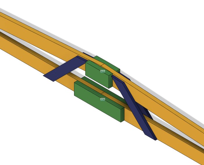
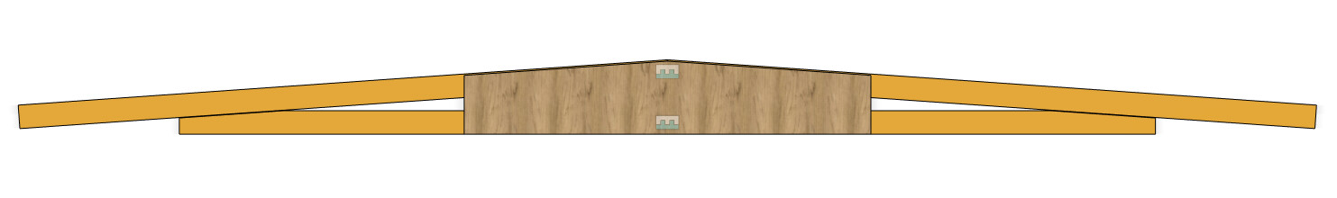
Konstruktionen är enkel och förhållandevis klen - ser ut i princip så här:
Själva takstolen (gul) är i dimension 145x45, laskarna (grön) är i dimension 145x45 och snedstävorna (blå) är i dimension 22x95. Spännvidd på takstolen mellan upplagen på väggarna är c:a 6m
Den nedre lasken är spikad med 12st 4" spik och den övre lasken är spikad med 8st 4" spik. Snedsträvorna är spikade med två 4" i vardera bjälke. Det som har hänt över tid är att framförallt spikförbandet i den nedre lasken har börjat ge efter så det blir en nedböjning på mitten - var 120mm innan stämpning och då utan annan last än råspånt och tjärpapp.
Spontant känns hela utförandet av skarvningen som en väldigt svag punkt men frågan är hur man kan bygga om detta så taket håller för snölast över tid.
En arbetshypotes är att ta bort snedsträvor och lask på en sida i taget och ersätta dessa med en skiva konstruktionsplywood som förankras med lim + spik eller skruv och sedan repeterar man processen med nästa sida av takstolen.
En 1200mm bred skiva skulle i princip överlappa hela nuvarande konstruktion men frågan är om en 20mm K-plywood och förbanden blir starka nog?
Har sökt information om takstolskonstruktioner men inte hittat något relevant för denna konstruktion - i dag så är det ju dessutom helt andra krav och möjligheter att optimera material, skarva med spikplåtar som pressas in i materialet etc.
Är öppen för alla förslag och ideer så länge det går att realisera från undersidan. Undviker helst någon tvärgående balk då det drar med sig en massa annat stök
The access that can be created with reasonable effort is from below since the facade is brick, and on one side, the roof truss extends about 1.5m to create a canopy. The visible ends of the roof truss are also part of the building's "design," so there's some aesthetics to consider as well.
Snow zone 3.5 here makes it a bit more challenging
Yes, then it is indeed too weakly constructed from the start. As you have probably already realized...
It's not possible to access and bring in new ones from the direction of the screen roof either, then?
One way is probably to let a new beam rest on an extra post by one of the walls.
I have a free-spanning glulam beam around 6 meters, but then we're talking about a piece measuring 90x360mm.
Mmmm, different rules 50 years ago and not as strict as today.
Need to think a bit more, one option is to support with a beam right under the joint in the subframe, but it involves some tinkering and is not entirely trivial to fit.
The simplest solution would be to just restore the function to how it was before; the settling has happened in recent years, so it's likely the wear over time with recurring deflections that is causing the nail joint in the subframe to fatigue.
It would have been interesting to be able to calculate/simulate what, for example, a 1200mm long double K-plyfa that is nailed/glued would do for the strength. It would also be possible to make an even longer midsection, but the question is whether it adds anything? Practically, it would be feasible to double the thickness of the entire truss with 2x24mm K-plyfa.
Hello
I'm sure you'll sort that out.
One thing to consider when you prop up the roof and then reinforce it is that the reinforcement will only bear the load until it settles back to the same position as before the reinforcement, and then it might be too late.
Now, this is usually not a problem you need to worry about, but understanding the mechanisms makes it easier to do it right.
/W
I'm not quite following, so please elaborate on how the reinforcement only benefits between a "zero position" and the sunken position.
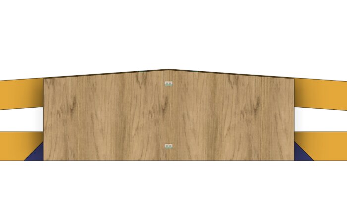
I'm not sure if I was unclear, but the idea I've been considering is to prop up each side of the ridge joint on the truss, clear away the scarf joints at the top and bottom as well as the braces, and then replace them with a custom-cut construction plywood on each side that's nailed and glued to the bottom and top chord (thinking that you would do one side at a time).
The width of the construction plywood could be anything between 1200mm, 2500mm, or several pieces so that it becomes a fully clad truss from the outer edge support on the wall.
It won't meet today's construction standards, but if a reinforcement becomes as strong as it was when the carpenter nailed together the garage in 1970, then we're back at "status quo," so any strength beyond that is a pure bonus.
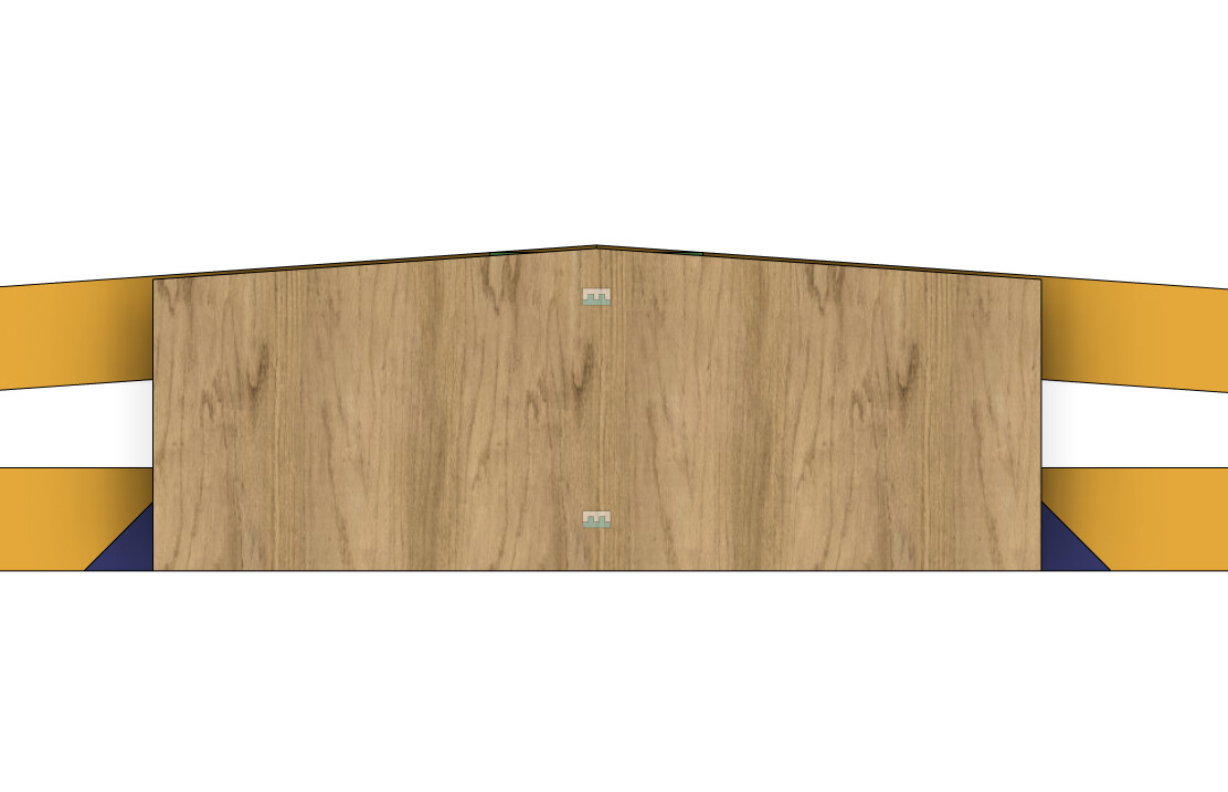
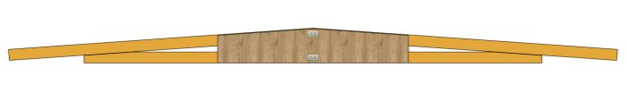
With a 2500mm long "plywood scarf joint," it would look something like this:
I haven't been able to check the condition of the joints at the supports, but if you're tinkering with the roof, then it's a small effort to also inspect these.
My logic says that the longer the splices, the better. There will probably be deflection anyway. Possibly, it might instead occur in two places, where the attachment of the splices ends.
Provided that the support is good, maybe another way would be to nail a type 480 cm long 21x195/170 on each side instead of k-ply.
What has given way? Is there a gap between the pieces that make up the subframe, is there a gap between the upper frame pieces, i.e., where the beams meet?
Has the upper frame bent downwards?
Are the screws pulled out/screw holes becoming "oval"?
The blue pieces on your sketch seem to be facing the wrong way to absorb the forces in the truss and press the subframe apart when there is a load on the upper frame, and do not support the upper frame against sagging in the middle.
If they have slid apart, you need to pull them together before screwing in a reinforcement, and if they have bent down, they probably need to be stiffer.
If you can push the upper frame back to the "normal position" and simultaneously pull the truss together so that any gaps between the parts in the upper and subframe close up, you could place vertical pieces between the upper and subframe (which keep them apart) and then screw on plywood that holds them together horizontally.
Then I don't think that plywood is much stronger against tensile forces than a board; half of the plywood's fibers run across the direction of tension.
What does the joint between the upper and subframe look like at the wall/support? Has that also given way? If so, it might require reinforcement there too.
Have dismantled a bit more of the ceiling so it's possible to see more of the roof truss, and it's a real truss construction with two "W"s, so the diagonal brace I first saw is one side of the "W."
From what can be seen, each "triangle" holds together neatly while the two central joints bend downwards and "gap" apart.
Can't see anything, but I guess the nails in the lower chord are moving sideways or have broken off, as the gap between the two halves was around 20-25mm when it sagged the most. That is, the lower chord slides apart under load.
That sounds good. Then it's probably "just" a matter of pressing up the roof trusses, pulling the parts together so the gap disappears, and then screwing on new reinforcements.
When we had builders who nailed the trusses together on-site (instead of ordering them from the factory, as agreed) with some anchor nails and nail plates, it was redone. Our constructor calculated on it, and we set large pieces of 15 mm K-ply on each side with "lots" of screws to hold it together.
They were 5 mm wood screws, 80 mm long, that were set from both sides so they went through the plywood, the beam, and then into the next plywood.
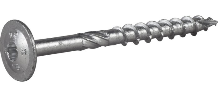
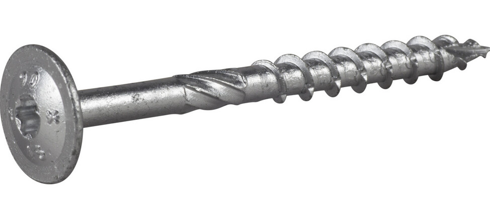
Glipan i underramen försvinner när takstolen nu är stämpad och lyft till normalläget så frågan är om det rent av räcker med att dra in rejäla konstruktionsskruvar i befintliga laskar? Har kört en del montage med ESSVE WAF och den är både CE märkt för lastbärande konstruktioner och riktigt trevlig att jobba med (finns ingen anledning att köra fransk träskruv längre).
I längd 100mm är gänglängden 50mm så så skulle man få hela gängan i underramens virke men utan genomträngning (virket är närmare 50mm än 45mm). Går man upp till längd 140mm för att få bett i lasken på andra sidan underramen så blir gänglängd 80mm varvid man då får 10mm utan ingrepp i underramen - frågan är vad som ger bäst resultat och i fall man skall gå på 6mm eller 8mm diameter på skruven?
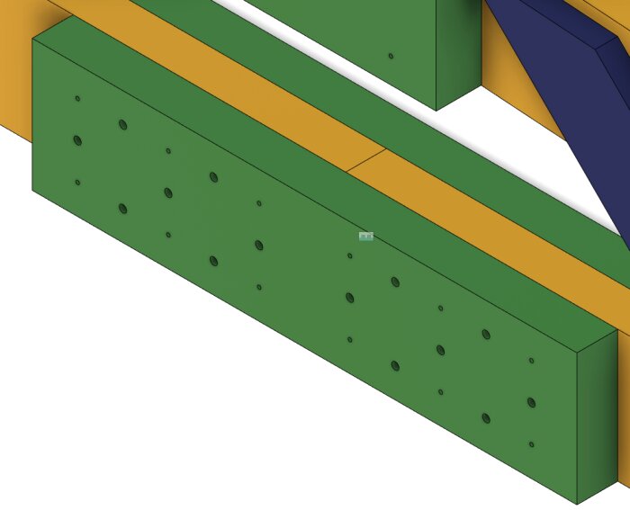
Nu sitter det 12st spik så det blir ju lite trångt men borde väl fungera bra att sätta en rad i mitten och så mitt mellan spikarna i befintlig rad likt detta:
(de små hålen illustrerar spikarna och de större hålen illustrerar tänkt läge för WAF skruvarna)
Med en fackverkstol blir det så vitt jag kan se blir det endast dragkrafter som skall tas om hand i detta förband.
Ett annat alternativ kanske kan vara ett par genomgående sexkantskruv med stora fyrkantbrickor?