26,164 views ·
22 replies
26k views
22 replies
Mold for square plinth?
Hi!
Does anyone have a good idea on how to construct a reusable mold for square footings (i.e., square cross-section)? They should be 1500 mm high and 200 x 200 mm.
There will probably be quite a lot of forces considering the height of the footing?
//fk
Does anyone have a good idea on how to construct a reusable mold for square footings (i.e., square cross-section)? They should be 1500 mm high and 200 x 200 mm.
There will probably be quite a lot of forces considering the height of the footing?
//fk
Make 4 walls out of, for example, marine plywood, and fasten them with some screws so the shape holds together.
Then take one or more straps and wrap them around your construction.
The straps will hold your form together when you pour in the concrete.
/ATW
Then take one or more straps and wrap them around your construction.
The straps will hold your form together when you pour in the concrete.
/ATW
I've been considering that, it might work. I found a picture of plinths that seem to be about 1.5 meters high and the form looks very simple (attached).ArneTW said:
Maybe there aren't as many forces as I think??
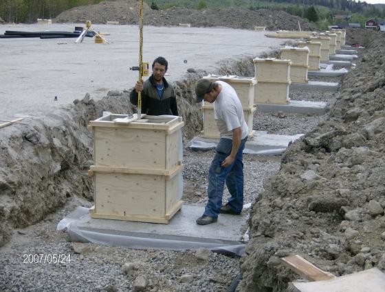
Simple is good, in the picture it looks like they have used battens to hold it all together... I like ratchet straps so I would use one to be on the safe side.
If you are going to cast freestanding like in the picture, you should think about how to prevent the concrete from flowing out from underneath... the form will tend to float up, so there is a risk that you get concrete on your feet.
/ATW
If you are going to cast freestanding like in the picture, you should think about how to prevent the concrete from flowing out from underneath... the form will tend to float up, so there is a risk that you get concrete on your feet.
/ATW
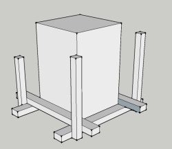
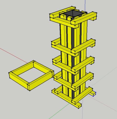
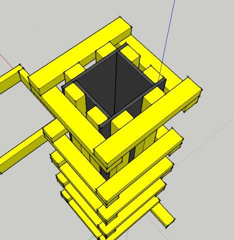
In principle, it's okay, but the transverse joists should be a few decimeters longer so that you can place a standing joist outside the horizontal joists. In this way, you lock the horizontal joists so they can't slide outward due to the pressure.
There will be significant pressure at the bottom of the mold since concrete is quite heavy... about 2.4 tons per cubic meter or so...
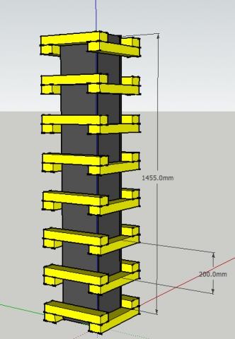
EDIT: Here is a picture that explains my standing joists. I didn't bother drawing all the form locks, but you probably get the principle.
There will be significant pressure at the bottom of the mold since concrete is quite heavy... about 2.4 tons per cubic meter or so...
EDIT: Here is a picture that explains my standing joists. I didn't bother drawing all the form locks, but you probably get the principle.
Last edited:
About concrete casting and formwork, I know nothing...
But physics, that I know!
So, therefore, I can tell you that the pressure at the bottom of your form will be 1.5 * 9.81 * 2400 / 10000 = 0.35 kg/cm². This is regardless of whether you make the form 100x100mm or 2x2 meters!
(assuming Fasting65's density figure, which seems reasonable).
This pressure acts both against the ground and the form walls at the bottom of the form.
It might be best to convert the pressure to 35kg / square decimeter to make it more understandable what forces we need to handle.
If you put a crossbar according to the image in post #6 with cc400mm, the force that wants to tear the bar
2 * 4 * 35 = 280 kg.
With cc200 = half = 140kg.
(approximately, as the force decreases higher up...)
If you make crossbars, for example, standing 45x120-145 and fasten them to each other with two M12 bolt connections at each joint, it should hold quite well.
But the question remains, how much will the board bulge between each crossbar, what is the minimum cc required?
Last edited:
OK, thanks!
I thought one could cheat a bit here, I can live with the casting being a bit wavy because the plywood buckles. However, it would be extremely unfortunate if the whole form collapses... so no shortcuts.
The studs are 45 x 70. The horizontal supports are spaced at c/c 300 at the bottom and c/c 400 at the top and are screwed together with bolts and nuts (M10?).
The vertical studs are screwed into the plywood and the horizontal studs.
The horizontal studs would actually be stronger if they were turned 90°, but I thought it would be good for them to have a large surface against the plywood.
This is topped with a couple of tension straps.
The plan is to first cast a slab with a protruding rebar in the small form 500 x 500 x 195 mm. Then place the large form on the small one, align it, and screw it onto the small slab's form.
Should work? Too complicated?
By the way, how do you calculate the pressure on an entire side panel? Some integral or??
//o
Integrals are probably overkill for a completely linear relationship.Fetkubrick said:
Pressure at the bottom/2 * area = (35kg /2) * 15 * 2 = 525 kg.
Your attached sketch feels quite solid to say the least.
")
I doubt anything will give way with that form.
I don't think the surface area 45mm vs 70mm matters here.Fetkubrick said:
Ratchet straps feel overkill.
Last edited:
Make the horizontal crossbars a few cm longer, so the nail and screw don't come so close to the endgrain, 4 cm longer is definitely enough, i.e., 2 cm pbs.Fetkubrick said:
Then nail together two of the joints with 4 pcs 4" nails, 100mm x 3.4 (or equivalent screw dimensions), the other two joints you connect with 1 pcs M10 bolt + nut. You only need to open one side.
Each nail can handle at least 70 kg.
http://www.traguiden.se/TGtemplates/popup1spalt.aspx?id=720&contextPage=1458
Last edited: