Hello! Questions .:
1) Can the wall be placed at the outer edge of the L-element, or should the wall be placed a bit in on the floor?
(The outer wall will go straight down - alternatively - a small sulfoot that protrudes.)
2) When the floor is cast - How is a "lip" that prevents the wall from being pushed in most easily created?
Background .:
Considering building an extension in two stories + basement.
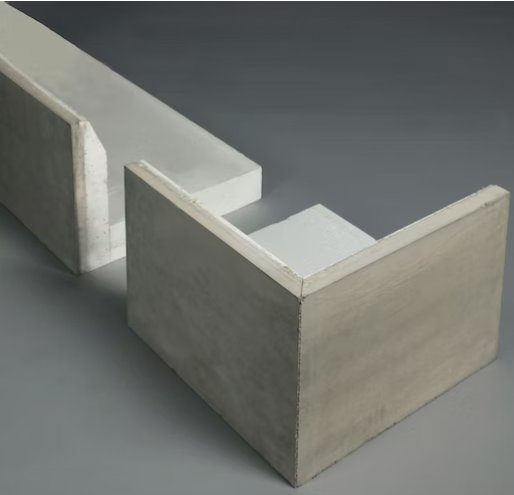
Planning to use insulated L-elements as edge beam
In these L-elements, there will be insulation and a cast floor.
Above the "floor," a wall of LECA blocks (e.g., 190*190*590) will probably be built
(it might eventually end up being a cast wall or...)
Why would you want edge elements if you're going to build a basement? Wouldn't it be cheaper and easier to pour a footing and build up from there? Then you don't have to worry so much about the strength of the edge elements. You can pour a slab (equally well-insulated) inside the wall later if you want.
It will (probably) be cheaper - but the current idea is "only" an extension of 6 x 3m
Easier? Avoid building a form with L-elements.
If you choose "form" there should be insulation in the form - also quite a bit of work...
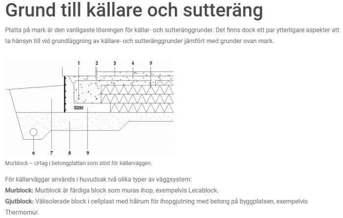
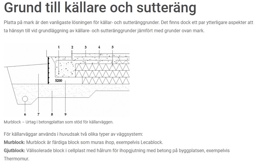
The strength S200 of the L-element should not be a problem.
Otherwise, unwanted torsional forces might occur - from the wall and house, if the wall is placed along the edge beam?
You're making a bracket that should be sized according to the linear load the wall has. Eccentric placement over the bracket can create torsional forces and cracks in the slab. Reinforcement with edge stirrups in the bracket is done to reduce that risk. However, if you are going to build a masonry wall, the load increases compared to a wooden wall, so you probably need to calculate that.
If you're building a basement, you're down to frost-free depth, I assume, then you can transfer the loads directly onto a concrete sill, or even sill blocks in leca?
You create a vot that should be dimensioned according to the line load the wall has. Eccentric placement over the vot can create torsion forces and cracks in the slab. Reinforcement with edge links in the vot is done to reduce that risk
I'm not very familiar with this... (hence my questions)
A "vot" - is it the same as "edge beam"?
"line load" - Is it the same as the pressure from the wall and house?
If I understand this correctly - The wall must be placed directly over the edge beam reinforcement (and nothing else). This makes it difficult to get an even wall and avoid the "edge beam" sticking out.
(If the edge beam and masonry wall align, it's easier to insulate the basement wall with e.g. pordrän)
Is it possible to avoid the protrusion from the edge beam?
A good description of the "challenge" with L-elements in construction. It won't be the same load as in the example, but the problem is well described.
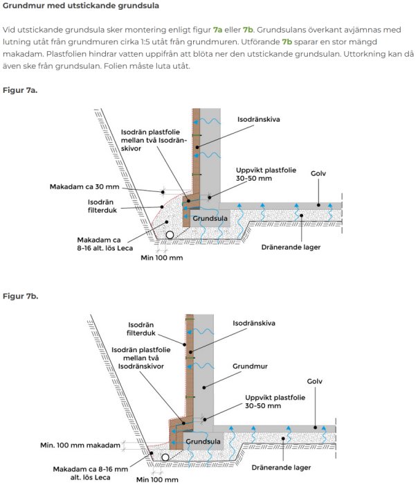
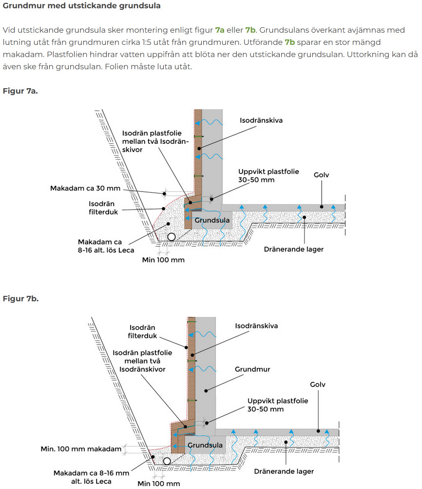
However, the question remains whether it's possible to avoid the "footing edge" outside the foundation wall. In the corner between the footing and the wall, there can be problems if water remains and stays.
I thought that Isodrän's work description describes different types of "basement walls" quite well. (but they mainly deal with basement wall insulation - not designing basement walls) This example (from Isodrän) with a protruding footing -- I wanted to avoid this time.
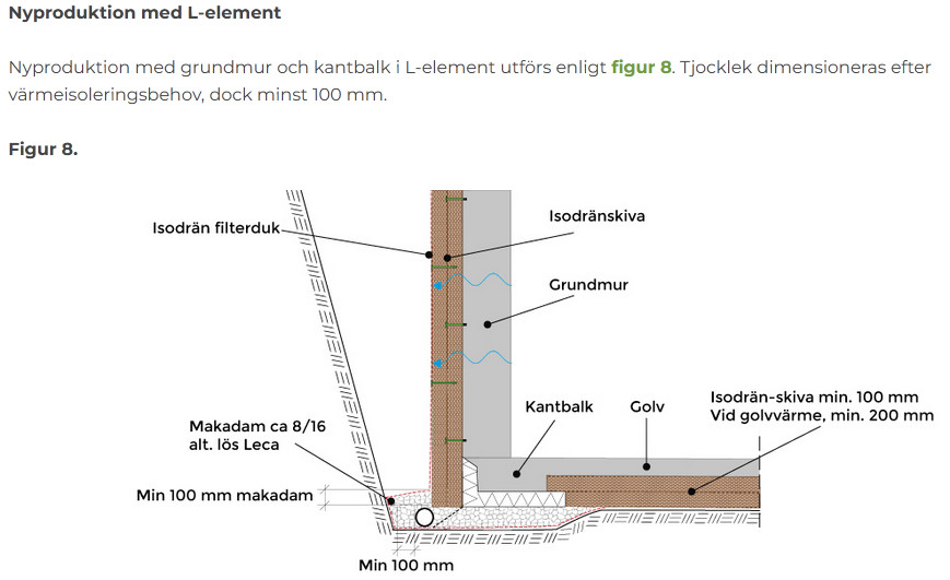
They also have an example of new construction with L-elements (avoiding the protruding footing) In this case, the wall is not placed over the edge beam. (also from Isodrän).
I have placed the leca wall at the outer edge of the foundation of my house, and it has gone well. It's a bit like having your own L-element but with concrete and Leca.
The strength of the sulfoten lies in the reinforcement (not the concrete). If you cast the sulfoten yourself, the reinforcement (the stirrups and the longitudinal reinforcement bars) ends up significantly lower. It can be placed 3cm from the outer wall (which is not the case with an L-element). I haven't measured how thick an L-element with a height of 40cm is - but maybe the L-element is 10cm thick - Then the reinforcement in the edge beam - which is supposed to handle both pressure and torsion - starts 13cm from the outer wall. (i.e., there are only 7cm left of the LECA blocks). But maybe there is reinforcement in the L-elements that solves part of the problem?
The drawing from Tjällden looks OK.
Three experiences from our extension with a basement, we used L-element:
Use XPS foam board at the bottom, it absorbs less moisture than EPS foam board.
Have a support heel about 10 cm on the slab that absorbs forces against the wall, visible on the drawing from Tjällden, some manufacturers don't include it.
Use 20 cm Isodrän/Pordrän all the way up to ground level. The guideline says (at least) 20dm at the bottom and 10 cm higher up towards the ground surface. It's a small extra cost to have 20 cm, and it provides better insulation and moisture protection.
It was a bit like the drawing from Tjälldén that I was thinking of initially. But then I started to wonder - it probably only applies to "garages" with "slab on grade"... (a relatively low load on the edge beam). Now, in this case - a basement with a masonry/cast (heavy) wall about 2.5m high and two wooden floors plus roof load and snow weights.
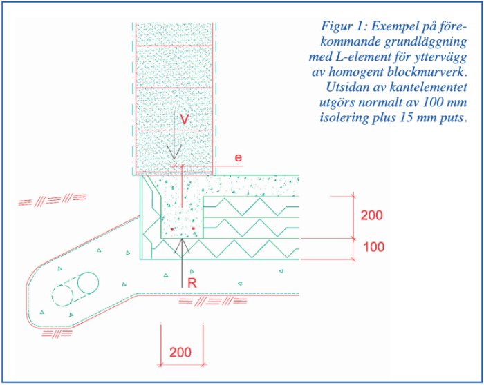
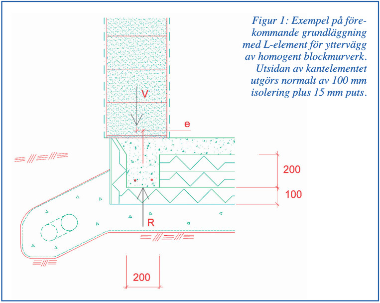
In the document from konstruktioner.se that @Hutton links to (L-element.pdf), a "torsion problem" is highlighted. In my case, the L-element might be at its load capacity for long-term load (I haven't calculated the forces yet). The other "problem" is that the center of the load from the house and wall will be outside the reinforcement in the edge beam (admittedly distributed over the entire LECA block - 190mm).
I thought the sketch from the above PDF describes the problem well.
As mentioned, the force "V" will land on the L-element and the counterforce "R" on the inner edge of the LECA wall. In my case, the distance "e" will be larger with this type of solution and create greater torsion. But I haven't considered if the L-element can be part of the "edge beam's" strength. Or if the problem can be managed with more/thicker reinforcement in the edge beam.... (maybe it's easiest to make a "projection" on the foundation foot and deal with the problems that solution brings instead?)
It was a bit like the drawing from Tjälldén that I initially thought of. But then I started to consider—it probably only applies to "garages" with "slab on ground"... (a relatively low load on the rim beam) Now this case involves—a basement with a masonry/cast (heavy) wall with a height of about 2.5m, as well as two wooden floors and roof load and snow weights. In the document from konstruktioner.se that @Hutton links to (L-element.pdf) a "tipping problem" is noted. In my case, the L-element might be at its load limit for long-term load (haven't calculated the forces yet). The other "problem" is that the center of the load from the house and wall will be outside the reinforcement in the rim beam (albeit distributed over the entire LECA block - 190mm). I thought the sketch from the above PDF describes the problem well. View attachment 655291 As mentioned, the force "V" will end up on the L-element, and the counterforce "R" on the inner edge of the LECA wall. In my case, the distance "e" will be larger with this type of solution and give greater torque. But then I haven't considered whether the L-element can be part of the "rim beam's" strength. Or if the problem can be handled with more/thicker reinforcement in the rim beam.... (maybe it's easier to make a "projection" on the sulfoot and address the problems that solution brings instead?)
Click here to reply
Vi vill skicka notiser för ämnen du bevakar och händelser som berör dig.