4,772 views ·
26 replies
5k views
26 replies
Force that pulls screw out of wall
Hello everyone,
I'm stuck with a simple mechanics question, sigh.
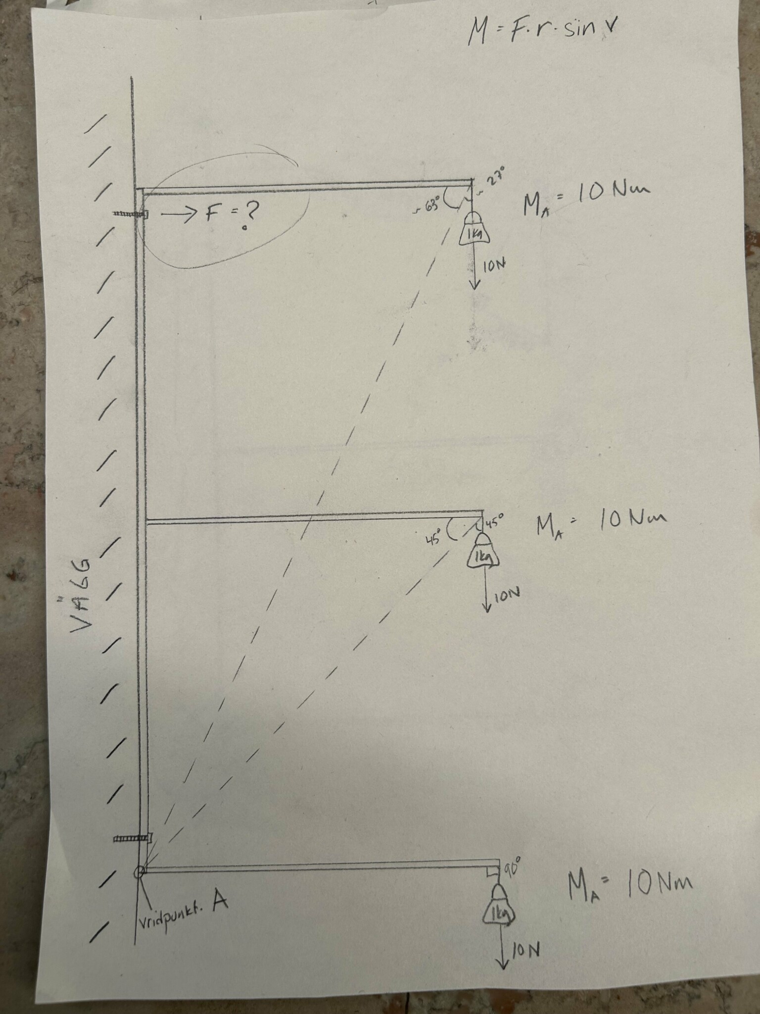
I'm trying to calculate the force acting on the upper attachment of a bracket with three shelves. That is, the force that will pull the screw out of the wall when the shelves are loaded.
I thought one should calculate the torque at the pivot point (at the bottom of the part of the bracket that is against the wall).
I understand there are many other forces involved, but assume the bracket is hinged at that point. Disregard the lower screw in the picture.
I find that all the shelves contribute the same torque, can that really be accurate? Am I calculating wrong?
How would you calculate the force?
Best regards,
Johan
I'm stuck with a simple mechanics question, sigh.
I'm trying to calculate the force acting on the upper attachment of a bracket with three shelves. That is, the force that will pull the screw out of the wall when the shelves are loaded.
I thought one should calculate the torque at the pivot point (at the bottom of the part of the bracket that is against the wall).
I understand there are many other forces involved, but assume the bracket is hinged at that point. Disregard the lower screw in the picture.
I find that all the shelves contribute the same torque, can that really be accurate? Am I calculating wrong?
How would you calculate the force?
Best regards,
Johan
Best answer

The devil is in the details. It's this "simple mechanics question" that sometimes oversimplifies the problem more than one might think. If the shelf really looks like the sketch, the back will be flexible. Therefore, you might get a greater force on the upper screw when loading the top shelf. On the other hand, if it's a shelf with sides, it won't bend significantly. Your calculation is correct. And as long as the shelf is reasonably rigid and secured, the calculation also aligns with practice.
If everything is rigid, there will be 5N from the bottom shelf, 10N from the middle, and 15N from the top in the extraction force on the upper screw...
The moment arm for the screw is 2m
for the bottom 1m for the middle 2m and the top 3m...
/ATW
The moment arm for the screw is 2m
for the bottom 1m for the middle 2m and the top 3m...
/ATW
No, that is not correct. See previous post.A ArneTW said:
R RiKr said:
Hi,A ArneTW said:
Thanks for the answer!
I don't understand how you are calculating, but I would like to understand if you could perhaps explain further, show?
Best regards,
Johan
take each shelf separately...Attefallshuset said:
I assume each shelf is 1m and the distance between them is also 1m.
calculate the moment around your point A.
Bottom shelf
1m * 10N = 2m x XN, X=5N
shelf2
(1m+1m)*10N=2m*XN, X=10N
shelf3
(1m+1m+1m)*10N=2m*XN, X=15N
add to get 30N.
The fact that the shelves are 90° outward doesn't matter... You might as well think that they are standing straight up.
I'm ignoring all self-weight etc., as well as shear forces/friction, and everything is 100% rigid.
/ATW
But does all the force really come straight out of the hole (according to the force arrow)? I think the direction of the force is important when mounting something.A ArneTW said:take each shelf separately...
I assume each shelf is 1m and the distance between is also 1m.
calculate the moment around your point A.
Shelf at the bottom
1m * 10N = 2m x XN, X=5N
shelf2
(1m+1m)*10N=2m*XN, X=10N
shelf3
(1m+1m+1m)*10N=2m*XN, X=15N
add to 30N.
The fact that the shelves are 90° outward doesn't matter... You might as well think that they are standing straight up.
I ignore all self-weight, etc., and also shear forces/friction and everything is 100% rigid.
/ATW
There are other forces too... the shear force. That is, a force vertically down along the wall.T topmount said:
30N if it's one screw, but if you count with 2 screws, it becomes a value between 0 and 30N.
Then there's friction, etc.
You can make it complicated...
I understood that TS was asking about the force component that wants to pull the screw out of the wall...
/ATW
It is the projected distance between the weight and the pivot point A that is interesting. And it is the same for all the shelves. What are you adding? I claim that all three weights contribute with 10 Nm around A just as @Attefallshuset wrote in their sketch. And consequently, a total of 15 N pulling force in the direction of the screw.A ArneTW said:
I think you are wrong... The vertical position of the shelves matters in my opinion.A Avemo said:It is the projected distance between the weight and pivot point A that is interesting. And it is the same for all shelves. What are you adding? I argue that all three weights contribute with 10 Nm around A, just like @Attefallshuset wrote in their sketch. And consequently, a total of 15 N pulling force in the direction of the screw.
That is, if you add a shelf that is 1000m up, you would get a substantial addition and not just 5N extra...
You get 10Nm at each shelf attachment, but you cannot just move it down to A.
/ATW
In TS's theoretical and static model where "pivot point A" is a hinged support, it is so. In reality, it's of course more complicated, but if you think correctly, the model captures what is relevant.T topmount said:
Unfortunately, it doesn't matter that you think so. In this case, given the conditions we have, we reach moment equilibrium according to Avemos' post, i.e., the tensile force is 15N.A ArneTW said:
Hobby electrician
· Värmland, Molkom
· 26 137 posts
What was the answer, i.e., how do you reason to arrive at the solution?
First, you calculate the torque each shelf contributes in point A.Bo.Siltberg said:
Only the force component that is perpendicular to the lever arm contributes to the torque. That is, when you pull a wrench, only the force applied in the "direction of rotation" creates torque.
From this, you can trivially determine the torque contributed by the lowest shelf since this force is entirely perpendicular to the lever (the shelf). Torque = force × lever's length: τ = Fr.
The poster has the force 10 N and obviously concludes 10 Nm, which means we can deduce that the shelf length is 1 m.
For the second shelf, the poster imagines the angle back and shelf form an imaginary lever from point A to the point where the force attacks. However, the force does not then attack perpendicular to the imaginary lever, and the poster must therefore calculate the force component that is perpendicular to it, which is F⊥= |F| sin θ, where F is the force and θ is the angle relative to the lever. The angle is in this case 45°, so F⊥ = 10 × sin 45° = 10 × √2 / 2 = 5 × √2.
The angle 45° also reveals that the distance to shelf two = 1 m. The length of the imaginary lever is given by the Pythagorean theorem: c = √(a² + b²) = √(1² + 1²) = √2.
We can now calculate the torque contributed by shelf two: τ = Fr = 5 × √2 × √2 = 5 × √2² = 5 × 2 = 10 Nm.
The observant will note here the relationship between the force vector and the length of the imaginary lever and realize that the distance between the shelves can be eliminated from the equation. All shelves contribute the same torque regardless of height.
The total torque can thus be trivially determined to 3 × 1 × 10 = 30 Nm.
To then calculate the force F when the torque is known, we calculate backwards:
τ = Fr → 30 = F × 2 → F = 30 / 2 = 15 N.