I'm scratching my head over the construction of the load-bearing wall on our upper floor. I usually read most "is this wall load-bearing" threads as I find building construction interesting. But now I have my own question that I hope those of you with more experience can assist with.
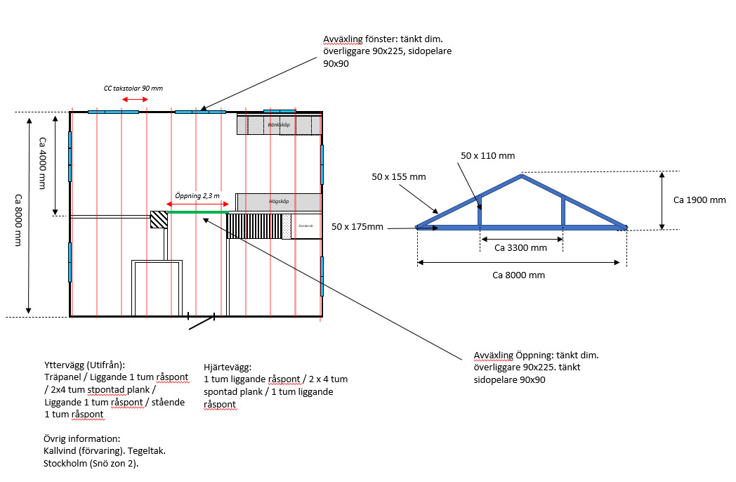
The house in question is from 1945. The center-to-center distance between the rafters is about 900 mm, which seems to be denser than I understood. You can see the type of construction below. The attic is a cold attic, so no upper floor. The attic will remain a cold attic/storage. The house is located in Sthlm, so snow zone 2, the roof is tile and will remain so. Not flat, but very low slope.
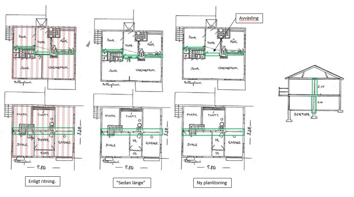
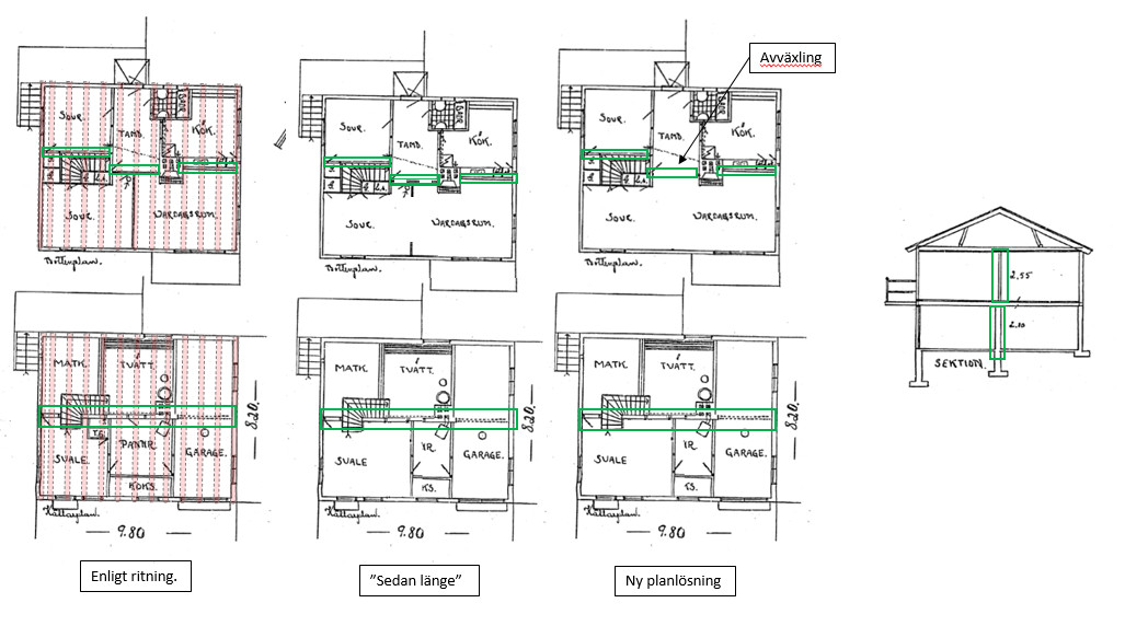
The only drawings the previous owners (the family who built the house) and the municipality have are what you see here in the post.
My question:
Assuming the Original drawing ("According to drawing"). We had planned to remove the wall between "Bedroom and living room" and the wall from the hall into "Bedroom and Living room" according to the "new floor plan".
The wall from the hall into the bedroom and living room has had two door frames previously. The entire opening from stairs to chimney is about 2.3m. I have marked what I interpret as the load-bearing wall in green.
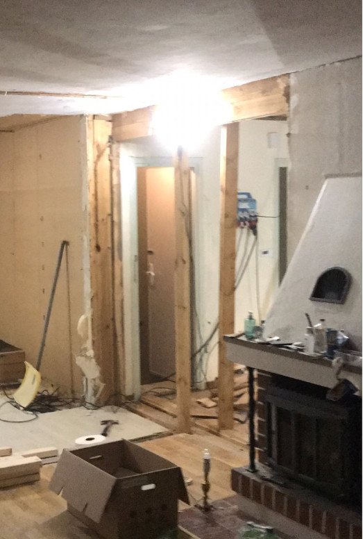
The header in the opening between the stairs and chimney feels very weak, I haven't measured dimensions exactly yet. But the overhead beam looks to be about 50x120-140mm. In the middle of the beam, between the door frames stands a stud, about 50x120-140mm. The overhead beam rests on side pillars of the same dimension. This must be part of the load-bearing wall and then load-bearing, doesn't this feel weak?
As a side note, I can mention that we are also planning to open up a window (2 m wide) in the outer wall directly opposite the front door and then Svenskträ's building descriptions suggest (with the same data as above and the addition of 4 m to the load-bearing wall (the load-bearing wall in the middle of the house which is about 8 m in that direction)) a header of 90x225 and side pillars of 90x90. The support for the window feels more robust than the support in the hall. I had thought to use the same dimensions for the support between stairs and chimney. Do outer walls and load-bearing walls take similar loads? Thoughts on this support?
The wall that divided the bedroom and living room was also opened previously. Not all the way up to the ceiling and about 1 m was left at each end (outer wall and wall towards the hall) according to the drawing. This wall was built more solidly: 13mm gypsum / 13 mm Tretex / Tongue and groove 50mm solid wall / 22mm horizontal boarding / 13 mm Tretex / 13 mm gypsum. Now it's only the tongued 50mm wall that can take any potential loads from the roof, but still. But this wall can't be load-bearing as it runs along with a rafter (if even that, not sure if a rafter runs directly above. All interior walls seem to be built like this, therefore I was a bit shocked when the wall I thought would be well built seemed a bit weak.
Here you can see a poor picture, will take a better one today. Note, I left a nogging under the header, so it looks higher than it is. I put up a post under the rafter before heading home.
If it has stood since 1945, why do you think it is too weak?
I thought the same, it has worked since '45. But because we are going to remove the opening and install a window in front of the same rafters, the load distribution will change, and then I thought if the original construction was too weak, or if I've misunderstood the house's construction, I want to know it now
The trusses are not self-supporting. On the contrary, they place a significant portion of the roof loads on the load-bearing wall. The house has a plank frame, where at least the interior walls consist of tongue-and-groove 2-inch planks. Through the tongue-and-groove jointing (and many large skew-nailed nails), a diaphragm effect is achieved. The jointing also braces the planks in the weak direction so they can withstand quite a bit of load. Removing the load-bearing wall at the hall opening of 2.3 m should not pose a major problem. Otherwise, I always recommend thinking through the floor plan first and seeing if there are alternatives that require less intervention.
Keep in mind that the cross-sectional dimensions are originally in inches. This can enhance understanding. c/c measurements are taken from center to center. When stud framing began to be used around 1950, a certain measurement standardization became necessary so that insulation and plasterboards, etc., would fit. Then, the common spacing for trusses became 1200 mm, which had previously been considered too large.
The trusses are not self-supporting. On the contrary, they place a significant part of the roof loads on the central wall. The house has a plank frame, where at least the interior walls consist of 2-inch tongue-and-groove planks. Through the tongue-and-groove (and many coarse skew-nailed nails), one achieves a panel effect. The tongue-and-groove also braces the planks in the weak direction, so they can withstand quite a bit of load. Bridging the central wall at the hall opening of 2.3 m should not pose much of a problem. Otherwise, I always recommend thinking through the floor plan first and seeing if there are alternatives that require fewer interventions.
Remember that the cross-sectional dimensions are originally in inches. That can increase understanding. c/c measurements are measured from center to center. When people started using stud frames around 1950, a certain measurement standardization became necessary so that insulation and drywall, etc., would fit. Then the typical truss spacing became 1200 mm, which had previously been considered too large.
Thank you for the answer Justus, it explains and clarifies a lot.
Do you have any thoughts on my planned bridging with 90x90 columns and 90x225 beams?
To calculate it, a dimensioning of the section and information about the snow zone are needed. 90x225 is at least in the right ballpark, I can't say more than that. 90x90 columns are sufficient, I can say that for sure.
To calculate it, you need a measurement of the section and information about the snow zone. 90x225 is in the right area, that's all I can say. 90x90 pillars are sufficient, I can say that for sure.
Thanks, I will compile all the information I have and get back to you later tonight.
To calculate it, a dimensioning of the section and information about the snow zone is needed. 90x225 is at least in the right range, I don’t dare say more. 90x90 pillars are sufficient, that I can say for sure.
Hello again.
I have tried to measure how it looks since there are no drawings. I have tried to include everything in a drawing. If anything is missing, let me know. Hopefully, you can verify or disprove the dimensioning of the opening between the stairs and the fireplace.

")
Viktor.J said: