3,254 views ·
5 replies
3k views
5 replies
Help interpreting Svenskt Trä's quick guide
I'm calculating a new deck and using this https://www.svenskttra.se/siteassets/6-om-oss/publikationer/pdfer/lathund.pdf
On page 19 it states that the joists' center distance should be at most pillar spacing/4. This means that if I add more pillars (reduce the pillar spacing), I should also place the joists closer together. Why is that? It feels illogical to me!
In my case, I plan to have 2.15 between pillars on a free span of 3.1m and a 45x220 beam. Okay according to page 19. However, I'm already fixed to cc 60 due to a previous construction, which according to page 19 is too much (should be max 2.15/4 = 53.75cm). To achieve cc 60, I would need 2.4m between pillars, which requires 70x220 beams….
But if I scroll down a bit to page 25; dimensioning of the joists, my free span is 3.1 m, which for cc60 requires 45x120 C24. Well then, I'm safe with my cc60 after all? Or?
They just want a margin so you don't overload the joists too much and get an unfavorable placement too far from a support. Further from a support increases the moment on the joist and results in more or greater deflection at a critical point, which then becomes between the posts. Therefore, they want to bring the c/c of the floor beams to a distance of post/4.
You can set c/c to 600 since 537 mm doesn't matter much in this context, you may get a greater deflection than usual (read 5 mm at maximum load). They should have accounted for 50 kg or 491 N/m2 in fixed load and 2 kN/m2 (203 kg) in free load, so you can assess how much you will be loading the floor, and you'll never reach 203 kg/m2 with furniture and people, so in other words, you can sleep soundly. Just don't place a grand piano or a 500 kg concrete table there.
The last comment about page 25 does not pertain to the joist in this case, only to the beams. They assume your joist can handle everything you load it with and focus only on the floor beams. The reason for page 19 is that they take into account moment in the joist and want to obtain supports from the posts.
Ok, so D/4 refers to ensuring that the load is always distributed over a certain number (4) of points along the beam.
If we take the example d=2.4m and cc600, we have four joists loading a beam between two posts. If I reduce d to, say, 2m, it means only three joists fall within d and thus fewer points that a given load is distributed on. Do I understand that correctly?
The equation must however be related to the dimension of the beam, right? Because the moment decreases in parallel with d, a given beam can withstand more load with a reduced d.
So: Since I am fixed at cc60, I should dimension the beam based on the assumption d=2.4. Given that I don't reduce the dimension of the beam, I can then without risk reduce d (the more the more stable the construction).
Am I thinking correctly? I don't plan to put a grand piano on it, but I can't guarantee that a pool will never be placed on it, so I don't want to skimp on the construction.
By the way; Bonus question on load-bearing capacity: The guideline says the deck should be at least 22mm thick, but doesn't differentiate between, for example, 28 or 34. I'm choosing between 28x145 and 34x145 and understand that the latter will be stiffer, but it's not a mountain I'm constructing, so a little (virtually unnoticeable) flex is okay. But should the choice affect the dimensioning of the joists in any way?
Absolutely right that they want to distribute over 4 points in their table on the dimensions for support beams; otherwise, their table would be huge and wouldn't fit in pocket format.
If you want 2.4 meters between the pillars and to meet the requirements for c/c 600mm, you will need to move up to glulam or another type of beam since they only include up to 220 high K24 support beams in their table.
See page 20 for glulam beams, but you will have to dig deeper for the same height.
Regarding the bonus question, you start with dimensions from where you have the load, i.e., the floor; then you check the thickness against c/c of the floor joists and then against the support beam, support beam against pillar supports, and then pillars against the ground. If you have a longer c/c than 600, you should increase to 28 or 34.
It's all about deflection that is acceptable. You don't want the floor to slope 1 cm between the joists if you're standing in the middle. That's what you'll get if there's too much distance or the construction is too low on the floor. Try with a 22 mm board, stand in the middle of it with supports at c/c 400, 600, 800, and 1000, and you'll get different deflections in the middle. The same goes for the support beam; it just takes up loads from more floor joists and a larger area of the floor.
I hope I'm clear; it's not easy without drawing sometimes.
I thought about this a couple more times. It is possible to get 3 points if the floor joists are placed directly on the piers. And since the only reason I can think of for the center-to-center distance between floor joists to decrease parallel to the distance between piers is to avoid the load being distributed over too few points, the equation should be in steps/intervals rather than linear.
Example: d=2m -> cc 50 cm. The worst scenario for the beam and a given load is if the floor joists are directly on the pier, as we then only have three points loading the beam. If I now reduce d to 1.9...1.8...1.7...1.6... nothing changes except that the moment against the piers decreases (the beam’s load-bearing capacity increases), as there still cannot be fewer than 3 floor joists between two piers. However, at d = 1.5, it becomes possible for there to be 2 points, and the local force against the beam increases (given an unfavorable load placement).
Therefore, the guideline should be that cc should be between d/4 and d/3, and my cc 600 at d=2.15 is, in other words, completely okay
With the reservation that I've completely missed the point
No, if a load is directly above the pedestal, there will be no moment in the support beam at all, i.e., a moment from 3 loads instead of 4, which you get with the support when the pedestal is midway between 2 floor joists.
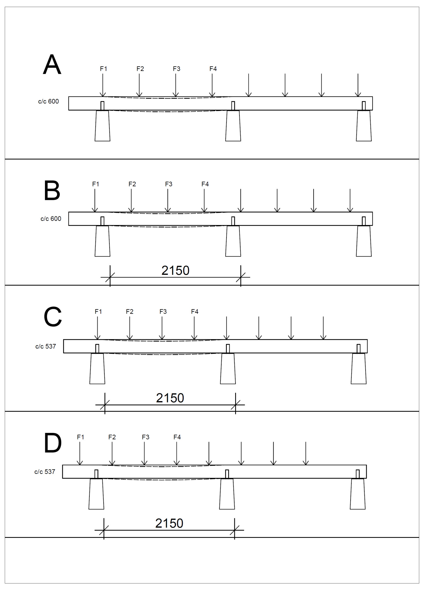
A moment is a movement, and when you stop the movement, you get a deflection. The force from the floor joists creates a moment in the support beam. (see fig could not resist drawing)
So they have D/4 to ensure you are safe.
Comment on figure,
In A and B, I have c/c 600 as you want, A is straight over the pedestal, and B is the worst case you can have with a load mid-way between pedestals, i.e., the longest distance to the support (will be the largest moment exponentially as you take force times distance).
In C and D, c/c is reduced to D/4 537 mm, which gives a lower load per F1 - F4 compared to A and B, as each floor joist in A and B should take up 0.6x1.55x2kN and in C and D 0.537x1.55x2kN
A and B F1 - F4 = 1.86kN + ,5kN = 2.36 kN
C and D for F1 - F4 = 1.66 + ,5kN = 2.16 kN
Difference 2.36-2.16 = 0.2kN or about 10% more in A and B.
When you have the worst-case scenario in both, you end up right between the supports, i.e., 2.15/2 = 1.075 m multiply this by previous results, and you get 2.53kNm for A and B and 2.32 kNm for C and D.
That is, C and D will have less moment than A and B.
Finally, I agree they use a blunt figure to calculate the correct cc distance, but adding a curve to read off for dividing different d by 3.5 to 4.5 in an exponential curve would just have been complicated.
Click here to reply