I am in the process of designing a ground stand for solar panels made of pressure-treated wood as I don't want panels on my house and can't find any ready-made stands at reasonable prices that don't feel flimsy or unsightly. The criteria for the construction are that it should be oriented East/West and have a relatively low building height. In the case below, the construction is only 1778mm above the support beam, so the total height is expected to be just under 2m.
I am now wondering if anyone has any opinions on my concept, especially the dimensions to withstand wind loads. Below you can see three images of what I have in mind.
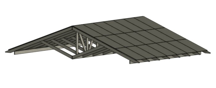
The inclination is 20 degrees, and the span of the solar panels is 5200mm. These are placed on 170x45x5400mm beams.
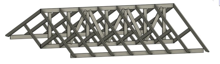
Everything rests on three support beams made of 195x45 beams, which in turn will be attached with 700mm piles not included in my model. The upright row of beams in the middle is 170x45 with an internal measurement of 1m, and all compartments are cross-braced with 170x45, which is clearer in the image below. The diagonal brace from the lower support beam to the support consists of 170x45 and extends to the middle of the span on the support. This is also at a 20-degree angle.
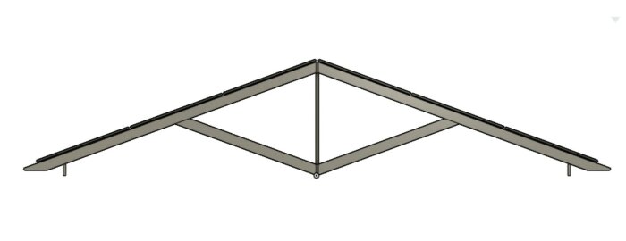
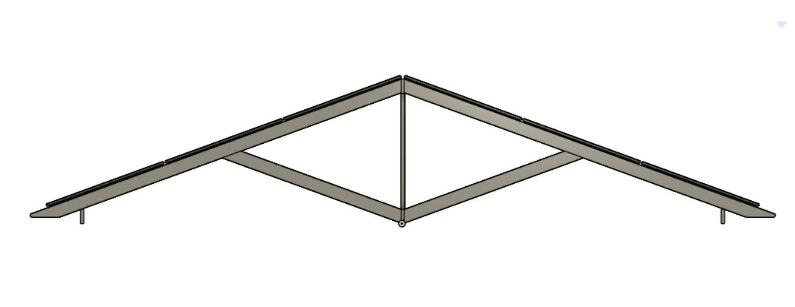
Above is a cross-section where you can see the construction of the upper support beam. The top rail consists of 170x45.
I plan for the entire installation to be placed on piles with minimal exposure above the finished ground since it will be in a fenced area. I will lay a rubber sheet under concrete slabs in front to keep the grass away (it will be in an old pasture). What is not visible in the image is the cross-bracing that will be done in the middle of the span on the 170x45x5400mm beams for increased lateral stability; I am thinking of using 70 or 95mm beams for this.
Everything will be screwed with ET-T construction screws and plate connectors with anchor screws for extra security.
All timber will be NTR class A. All fittings will be hot-dip galvanized and fastened at least class C4.
This is my first draft of the stand, and I gratefully welcome all input. Sometimes I have a tendency to over-dimension and go overboard, but I'm not exactly an expert on wind loads and have to admit my knowledge is somewhat lacking.
For those interested, the model is made in Onshape, which can be used for free.
I am designing a ground stand for solar panels in pressure-treated timber because I don't want panels on my house and can't find any ready-made frame at a reasonable price that doesn't feel flimsy or ugly. The criteria for the construction are that it should be in an East/West direction and have a relatively low construction height. In the case below, the construction is only 1778mm over the bearer line, so the total height is expected to be just under 2m.
I am now wondering if anyone has any comments on my concept, especially the sizing to withstand wind loads. Below are three images of what I have in mind.
[image]
The slope is 20 degrees and the span of the solar panels is 5200mm. These are placed on 170x45x5400mm beams.
[image]
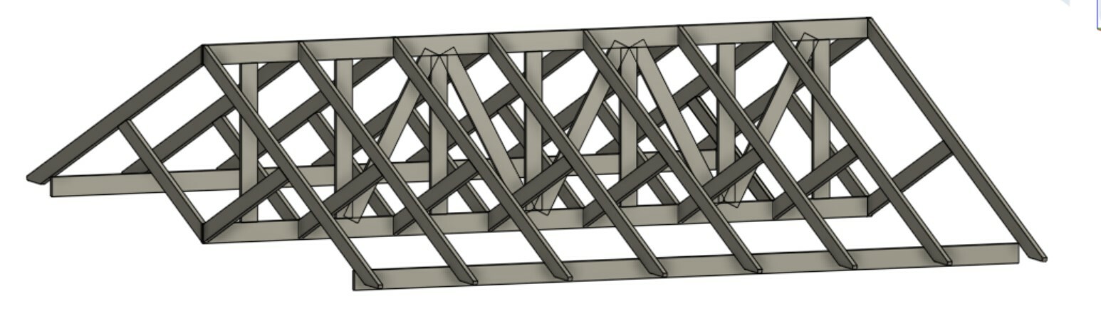
Everything rests on three bearer lines consisting of 195x45 beams, which in turn will be attached with 700mm foundation pillars that are not included in my model. The upright row of beams in the middle is 170x45 with an internal measurement of 1m, and all compartments are cross-braced with 170x45, which is more clearly visible in the image below. The diagonal brace from the lower bearer line to the support also consists of 170x45 and extends to the middle of the span on the support. This too is at a 20-degree angle.[image]
Above is a section where you can see the construction of the upper bearer line. The cap is 170x45.
I imagine the entire installation should be placed on foundation pillars with minimal visibility over the finished ground as it will be in an enclosed area. I will place a rubber membrane under concrete slabs in front to keep the grass away (the whole thing will stand in an old grazing field). What is not visible in the image is the cross-bracing that will be done in the middle of the span on the 170x45x5400mm beams for increased lateral stability, I am thinking of using 70 or 95mm beams for this.
Everything will be screwed with ET-T construction screws and hole plates with anchor screws for added security.
All timber will be NTR class A. All fittings are hot-dip galvanized and fixings are at least class C4.
This is my first draft of the stand and I gratefully welcome any input. Sometimes I have a tendency to over-dimension and go all out, but I'm not exactly an expert on wind loads and have to admit that my knowledge partially falls short.
For those interested, the model is made in Onshape, which is free to use.
Thank you for your time
//Anders
Looks sturdy, and no direct comments on the framework. What you do need to keep an eye on is the upward force that occurs when the wind blows against the "gable". To handle that, the construction must be sufficiently heavy and/or anchored in the ground. Then, of course, the wind can also blow against the "long side".
I'm a bit torn between mounting with 700mm plinth or ground screws from Jula. We have moraine soil here which is incredibly firm, but a plinth is more foolproof regarding its own weight. I probably need to start by calculating the construction's own weight before I decide which route to take. It might eventually be a combination with some plinths and a supplement with ground screws.
I'm torn between installing with 700mm concrete piers or ground screws from Jula. We have moraine soil here which holds on amazingly, but a concrete pier is more bombproof due to its own weight. I should probably start by calculating the construction's own weight before deciding which way to go. It might end up being a combination with some piers and supplementation with ground screws.
A ground screw needs to be reasonably long to have any decent capacity for tension. I would choose the concrete solution. Don't forget that the middle support bears double the load compared to the outer edges. What is the size? 100 sqm?
In total, it's about 35m2 per side, so a total of 70m2 panels. Concrete piles will probably be necessary since I will have to bring in an excavator for the cable laying of about 80m anyway. Then it's quite convenient with the increased self-weight with the piles. I will try to calculate the total weight of all the timber tomorrow to see where I end up. Admittedly, you see quite a few carports and patio roofs with considerably weaker constructions that have still been standing for many years, but I don't want to take chances with such an expensive installation just because it's boring to dig a little.
In total, it's about 35 sqm per side, so a total of 70 sqm of panels. Concrete plinths will probably be necessary since I have to get an excavator for cable laying of about 80m. Then it's quite thankful with the increased self-weight with the plinths. I will try to calculate the total weight of all the timber tomorrow to see where I land. Although you can see quite a few carports and sunrooms with much weaker constructions that have been standing for many years, I don't want to take chances with such an expensive installation just because it's boring to do some digging.
That's true, but if I recall correctly, the rules apply for 50-year winds, so it takes a strong wind to reach that.
If you make a base plate on the plinths that extends beyond the shaft, you get free weight from the soil.
Upward wind is in the order of magnitude of 0.5 kN/m2; so 35 kN in total. Equivalent to 3500 kg
Shouldn't one be able to account for some of the pull-out weight on the foundation block from the start? I'm thinking of a 700mm foundation block with a maximum of 100mm above ground, which has a weight of about 50kg, but it's conical in shape and should already provide a good resistance against the ground if you calculate pull-out force straight vertically. It's likely that there will also be a bending force over the foundation block, so it would need to twist out of the ground to come up, thereby needing to move quite a bit of moraine soil with it.
Are you thinking of casting a whole beam under the ground along the entire foundation row, or is it enough to drill in a few dowels at the bottom and cover it with a couple of bags of foundation concrete before backfilling?
Shouldn't it be possible to account for some of the uplift resistance in the pedestal from the start? I'm thinking a 700mm pedestal with a maximum of 100mm above ground already has a weight of about 50kg, and its conical shape should provide good resistance against the ground if you calculate the uplift force directly vertically. Likely, there will also be a bending load over the pedestal, so it needs to rotate out of the ground to be lifted and thus needs to move quite a bit of moraine soil with it.
What resists? It's the soil, and the soil is porous. Additionally, you are close to the surface, so no significant overburden pressure.
What I have overlooked is that the "trusses" face wind, so it becomes a combination of lift and horizontal load. But now it's getting complicated. So, I would have anchored for the entire lifting force perpendicular to the "roof." But this is a theoretical reasoning.
I am very grateful for your input here. At what wind speed do you arrive at 0.5kn/m²? Usually, when buying ready-made stand solutions, they calculate at 26m/s, but it doesn't hurt to design for slightly higher wind speeds. I did a quick rough calculation on the dead weight in panels and construction and it doesn't look too bad. I'll get back with figures during the day.
26 m/s would not be enough where I live near the sea on the west coast. I would probably want at least 40 m/s. So the local conditions are very important to know.
I live in central Skåne (Höör). According to Boverket, we have a reference mean wind speed of 25m/s during 10 minutes at a height of 10m for a 50-year storm. The terrain where I live is meadowland surrounded by forest. The longest distance to the forest is to the west and is about 1km to the tree line.
The weights in my construction are as follows:
Panel's own weight: 1260kg
195mm joists in bearing lines: 112kg
Trusses: 442kg
Standing 170mm joists: 67kg
18 footings 700mm: 1026kg
Total weight approx. 2907kg.
An alternative for better anchored footings is to use an earth auger (e.g. https://www.skurupsborren.se/) and first drill straight down a bit and then instead angle out several (2 or 3) holes to the sides. I did this for a flagpole and it worked excellently. This way, you also have undisturbed soil around the footing since you don't refill any soil but pour concrete directly into the hole. Imagine the shape as in the image below, but it might be difficult to get such an angle on the lower holes.
I am very grateful for your input here. At what wind speed do you arrive at 0.5kn/m²? Most of the time when you purchase ready-made stand solutions, they calculate at 26m/s but it doesn't hurt to design for slightly higher wind speeds. I did a quick rough calculation on the weight of the panels and construction and it doesn't look too bad. I'll get back to you with numbers during the day.
That's good 🙂. I made an assumption based on a load that felt reasonable, from a previous project. So I haven't calculated for your specific case. But to get a size order of the load.
I live in central Skåne (Höör). According to the Swedish National Board of Housing, Building and Planning, we have a reference mean wind speed of 25 m/s over 10 minutes at a 10m height for a 50-year storm. The terrain where I live is meadowland surrounded by forest. The longest distance to the forest is to the west and is about 1km to the tree line.
The weights in my construction are as follows.
Panels' own weight: 1260kg
195mm beams in load-bearing lines: 112kg
Rafters: 442kg
Standing 170mm beams: 67kg
18 footings 700mm: 1026kg
Total weight approximately 2907kg.
It will hold, my structure is weaker and has lasted for 5 years. What you should consider is that wood dries in the summer, which caused my panels to loosen and slide down, so I had to retighten, so don't skimp on screws/attachment points if you are using screws and washers. The farmer who has a field nearby sent a stone into my panels from the manure spreader in 2024 and he replaced it with 100kg of potatoes 😀. A tip is to look for inverters on Blocket when many are changing. The panels are around 1100 SEK new, and an inverter can be found for 7k.
Vi vill skicka notiser för ämnen du bevakar och händelser som berör dig.