28,718 views ·
28 replies
29k views
28 replies
Fastening of HEA beam???
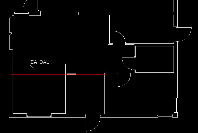
After much consideration, I have concluded that in my soon-to-be-completed house from the drafting stage, I need to support the mid-floor joists since I got spans of 6.5m. (see image)
My first thought was glulam!, but it would have to be something like 400X66 or something since I don't want a lot of glulam beams in the ceiling of the ground floor.
So it will have to be the old trusty steel...
I was thinking of supporting it by placing it on a load-bearing wall and on the other side on the tie beam! (see image for this vague explanation)...
ANYWAY!
now to the question:
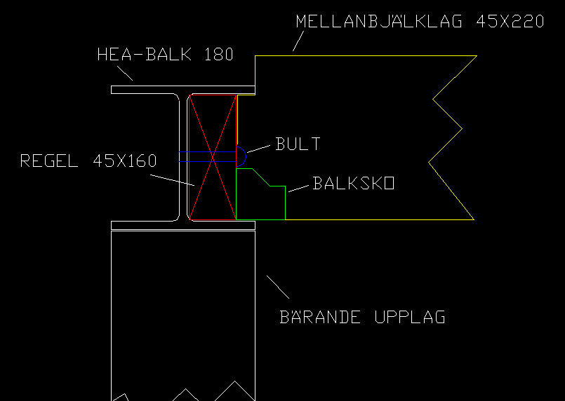
how do you attach the joists in the mid-floor to the HEA beam???
I’ve talked to a carpenter with 30 years in the industry and I’ve talked to my friend who is a site manager at Peab about this, and both have 2 different conclusions (which I find a bit strange both of them).
Look at the images, agree or come up with your own suggestions..
Thanks in advance!
My first thought was glulam!, but it would have to be something like 400X66 or something since I don't want a lot of glulam beams in the ceiling of the ground floor.
So it will have to be the old trusty steel...
I was thinking of supporting it by placing it on a load-bearing wall and on the other side on the tie beam! (see image for this vague explanation)...
ANYWAY!
now to the question:
how do you attach the joists in the mid-floor to the HEA beam???
I’ve talked to a carpenter with 30 years in the industry and I’ve talked to my friend who is a site manager at Peab about this, and both have 2 different conclusions (which I find a bit strange both of them).
Look at the images, agree or come up with your own suggestions..
Thanks in advance!

Now I'm a bit unsure if I understood correctly...
But you are planning to use 2-part floor joists?
In that case, I hope these joists are not part of the trusses... (maybe a two-story house)
If it's a 1 1/2 story or raised wall life, I don't think you can use any of the shown methods; you should probably have your beam under the floor joists.
But you are planning to use 2-part floor joists?
In that case, I hope these joists are not part of the trusses... (maybe a two-story house)
If it's a 1 1/2 story or raised wall life, I don't think you can use any of the shown methods; you should probably have your beam under the floor joists.
We followed option one, but with the addition that only a groove for the HEA beam was cut out in the floor structure, so the wood above the HEA beam is also retained. The two mid-floor pieces meet in the middle and have been very carefully nailed together with birch veneer on both sides. This mostly serves the function of holding the mid-floor together until everything else holding the house together is in place. Our beams are welded to steel posts in the interior walls but attached to wooden posts (three carefully nailed 2"x6" pieces) in the exterior walls as we felt steel posts would create too much of a thermal bridge. The construction is based on engineering drawings by engineer...who, by the way, himself thought we could have used 11 kerto beams instead...how nice is it to have such things protruding from the ceiling :")
thank you for all the answers and inspiring ideas!
I think I was a bit vague in explaining the type of house.
It is a 2-story villa with half the house 2-story and half 1-story, shed roof on the 2-story section and glulam floor in the 1-story part (cathedral ceiling). So you could say it is 2 building sections on the same slab, with a load-bearing wall as a separator. It is in the floor structure of the 2-story part where my intended reinforcement might be implemented.
Technically speaking, both floors are self-supporting in terms of distributing weights from the roof trusses, i.e., they are distributed in the exterior walls. This solution is likely because I want to avoid using the 2nd floor as a trampoline. (floor deflection).
Regarding the fastening of the beam, it will probably be some form of steel column at one end, and the end resting on the wall plate I had hoped to double or triple the vertical beams under the beam (45X170).
Concerning option 1,
there would likely be less strength if the floor structure has a larger dimension than the HEA-beam.
Maybe I should simply weld fixed beam shoes in the beam. Seems like the most logical way out... but what do I know!
These questions will be discussed and calculated by an engineer, but one wants to stay one step ahead...
Try breaking off the outermost dm of, for example, a 6". Let me know if you succeed
. Joking aside; the notch made for the beam is so close to the attachment point and so small in relation to the total height, so I guess it is relatively negligible. The strength of the HEA beam is much greater even though it is lower than the joist. However, keep in mind that it is difficult to pass HEA with pipes, etc.Hmm! I was thinking like this. If the wooden beam (which was intended to have the dimensions 45x220) breaks. Not that I actually believe it, but if we look at it hypothetically.
The breaking point will likely be where the cut is, because there the beam is only 152mm (if you have an HEA 180). Now, it seems a factor to consider is that the weakening is 86mm from the end grain and not in the middle of the wooden beam.
I might be wrong, but it doesn't feel quite "solid" to do it this way.

I would probably go for option 1 and possibly reinforce it by either placing a spkband on top or drilling some smaller holes and mounting angle brackets with bolts and nuts just to lock the wooden beams against each other.
Notching a bit at the ends is no problem. The timber dimension is chosen to prevent too much sagging in the middle, not to handle the load at the end. Wood bends quite a bit before it breaks, so in my opinion, there is no danger.
Notching a bit at the ends is no problem. The timber dimension is chosen to prevent too much sagging in the middle, not to handle the load at the end. Wood bends quite a bit before it breaks, so in my opinion, there is no danger.
Thanks for the tips!M.C. said:
Having steel here shouldn't cause any major problems when it comes to electricity, pipes, etc.
Then I don't know if it's me thinking wrong, but, M.C., how did you intend to place a 240-beam? In that case, I'll probably need to increase the dimension of the floor structure.
If I'm not mistaken, the 240-beam is 230mm in height, while I’m planning for a 220mm floor structure, right?
It seems like most people have used option 1, but the innovation mindset seems unfathomable among the country's all constructors! Though the alternative with fixed "bolted" angle irons seems interesting!
Grateful for all the answers!
Option 1 is given, that's normally how it's done! However, a tip is to make the notch on the underside 20mm higher up in the beam and the upper one the same (= lower the wooden beams 20 mm below the underside of the steel beam), then you can pass the beam with any electric conduits easily, as they are normally located in the sparse panel in the underside of the floor structure. Secure the beams to each other with a perforated strip over the beam so they remain stable during the construction process. If the floor structure needs to handle tensile loads, you can ask a blacksmith to make a bracket with a sturdy flat bar on top and two "forks" on either side of the beam to secure the beams. It doesn't need to be attached to the beam but simply rests on top instead. When we built, this was done on the trusses in advance, which could then be lifted into place easily without needing to thread them through the beam.
The rule is strongest at the attachment, so there should be no problems. Long before the ends fail, you'll have issues with the beams starting to look like bananas. In any case, you'll get ends that are about 160 mm. Compare that with my roof trusses made from 145 beams (single-story) at the truss factory
This indeed feels like a tip worth gold. I've refrained from placing certain outlets and switches in their natural spots because I wanted to avoid the hassle of getting past the steel beam. You can simply add 20mm support under the sill plate where it should lie and raise the posts at the same time (it's possible to support in 2 places). Now, it seems like all that's missing is the designer wanting to reinforce the slab due to point load... Well, there are still 3.5 months left until construction starts (if you can trust today's seasons), so there's time to correct certain changes...MrMagic said:
Now I'm lost again...
. If you have the HEA beam level with the bottom of the joists (as your drawing shows, the sparse panel is nailed under them. In that gap, you can pass electrical conduits - it's worse with larger pipes.A tip, however, is to make the notch on the underside 20mm higher up in the beam and the upper the same (= lower the wooden beams 20 mm below the underside of the steel beam), then you can pass the beam with potential electrical conduits in a simple way, as they are normally located in the sparse panel in the subfloor.
; after you've made your cutout you still have about 6" left...it's impossible to have the break point there when it's placed at the end. Nothing to worry abouthmm! I was thinking like this. that if the wooden beam (which, by the way, was intended to have the dimensions 45x220) breaks. Not that I really believe it, but if you look at it purely hypothetically.
then the break point will probably be where the cutout is because right there the beam is only 152mm (if you have an HEA 180). Now it is probably such that it's a factor to consider that the weakening is 86mm from the end grain and not in the middle of the wooden beam.