Hi,
I got help from a designer (at a building supply store) to calculate what beam I need to support a wall. Unfortunately, they only calculate in glulam, which makes the beam too high.
I have tried to find someone who converts glulam to steel but can't find anyone.
Is there anyone knowledgeable in this who can say what steel beam is equivalent to 115*315
The span will be about 3000mm, the beam should be 3250.
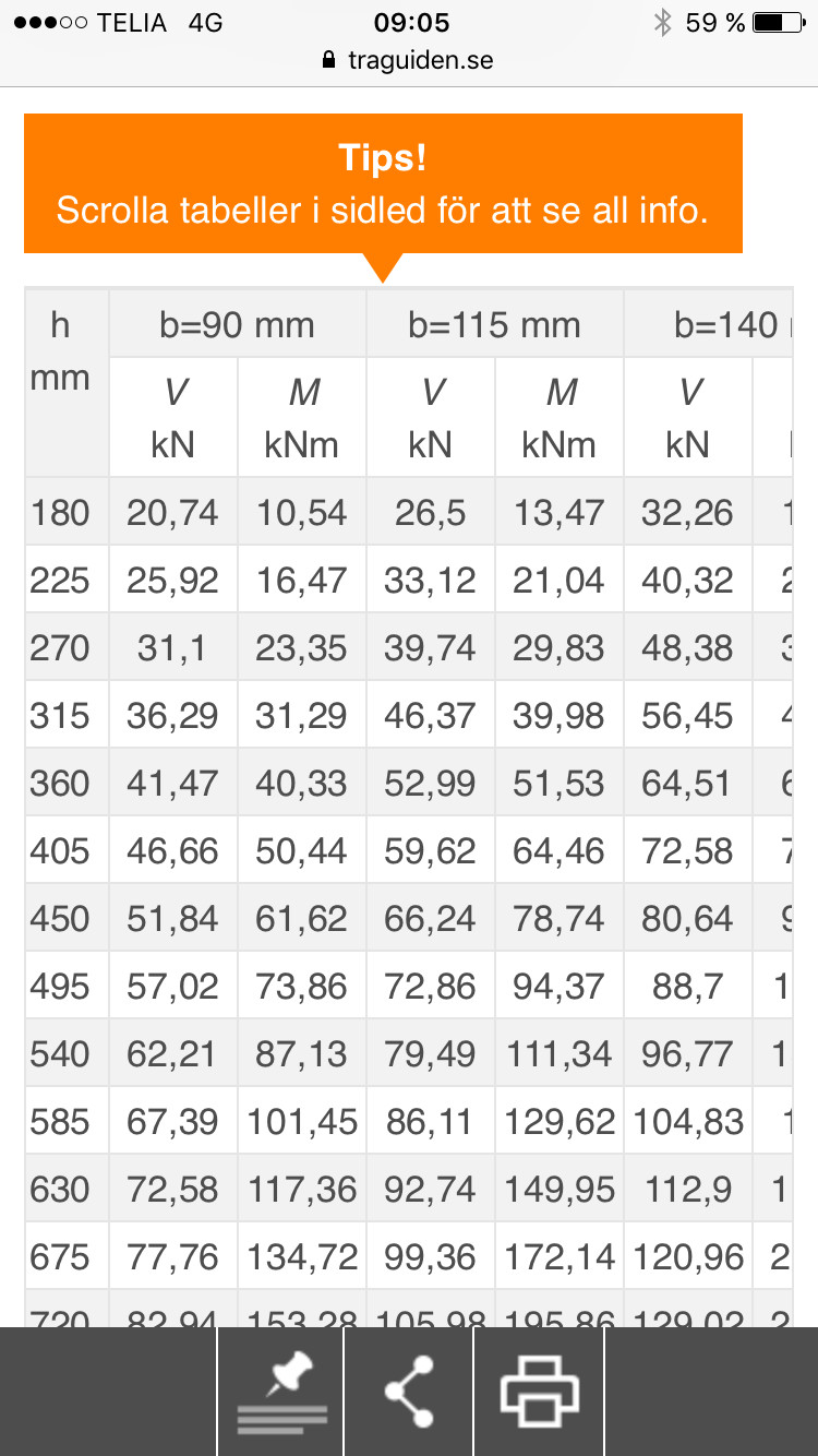
It is not possible to make such comparisons without knowing what should be determining, the breaking limit or the service limit (i.e., the deflection). Glulam and steel have completely different properties in these respects. A glulam beam of 115x315 can handle a maximum moment of about 40 kNm. With a span of 3 m, this corresponds to a distributed load of about 3600 kg/m. With this load, the glulam beam can also keep the deflection under 10 mm. To handle the load, an HEA 140 is sufficient, but to handle the deflection, an HEA 180 is required. However, I would like to question if the person who helped you really calculated it correctly. A 115x315 over 3 meters is quite substantial.
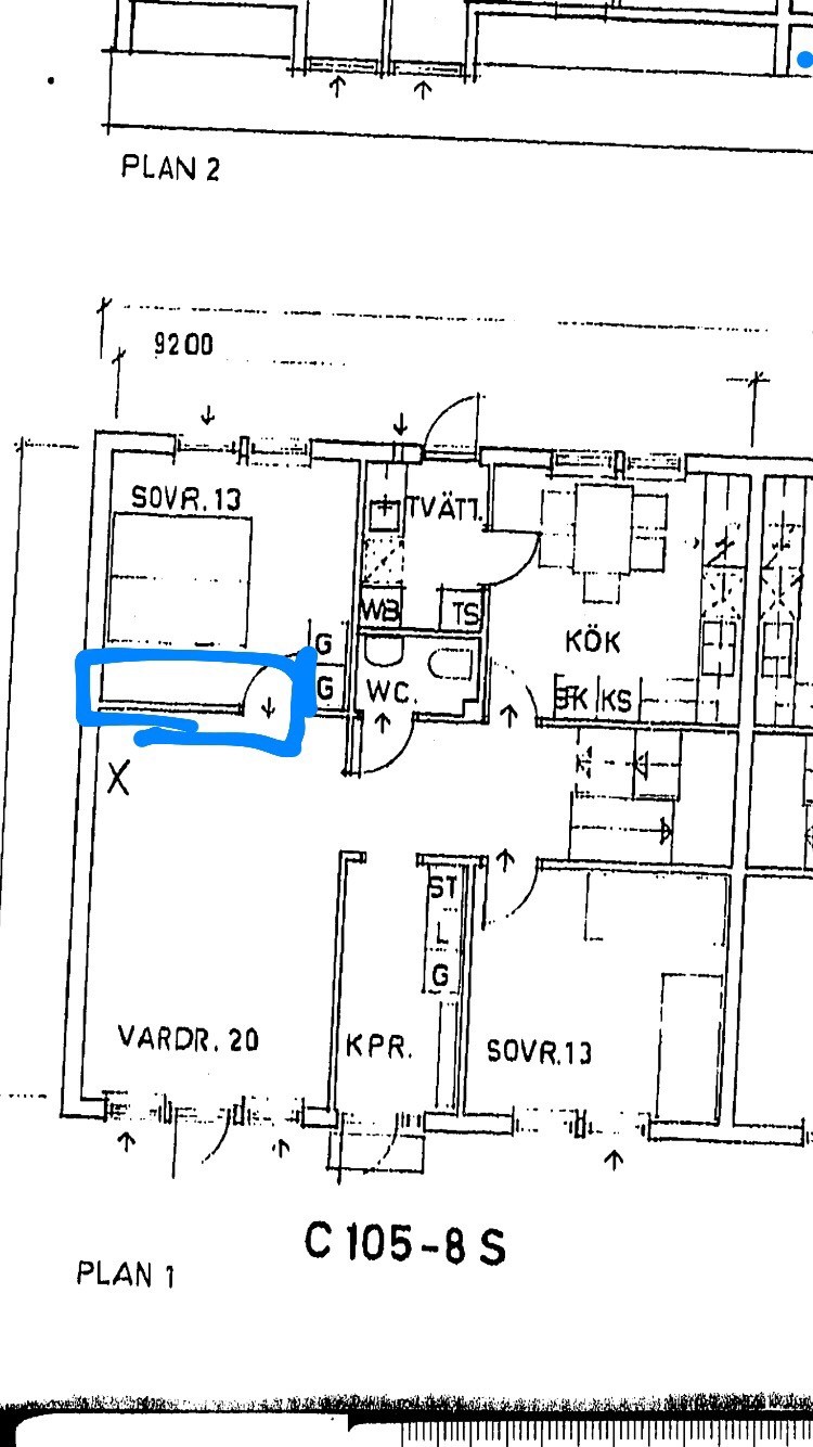
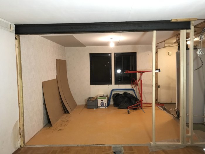
This wall is the one to be taken down. The opening will be 3000mm.
The width of the house is 9200mm. The roof has a 45-degree pitch.
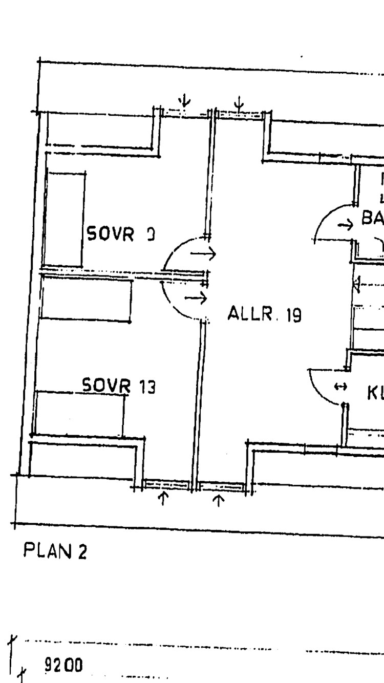
The upper floor looks like this
The floor structure is made of chipboard, essentially everything in the house is chipboard.
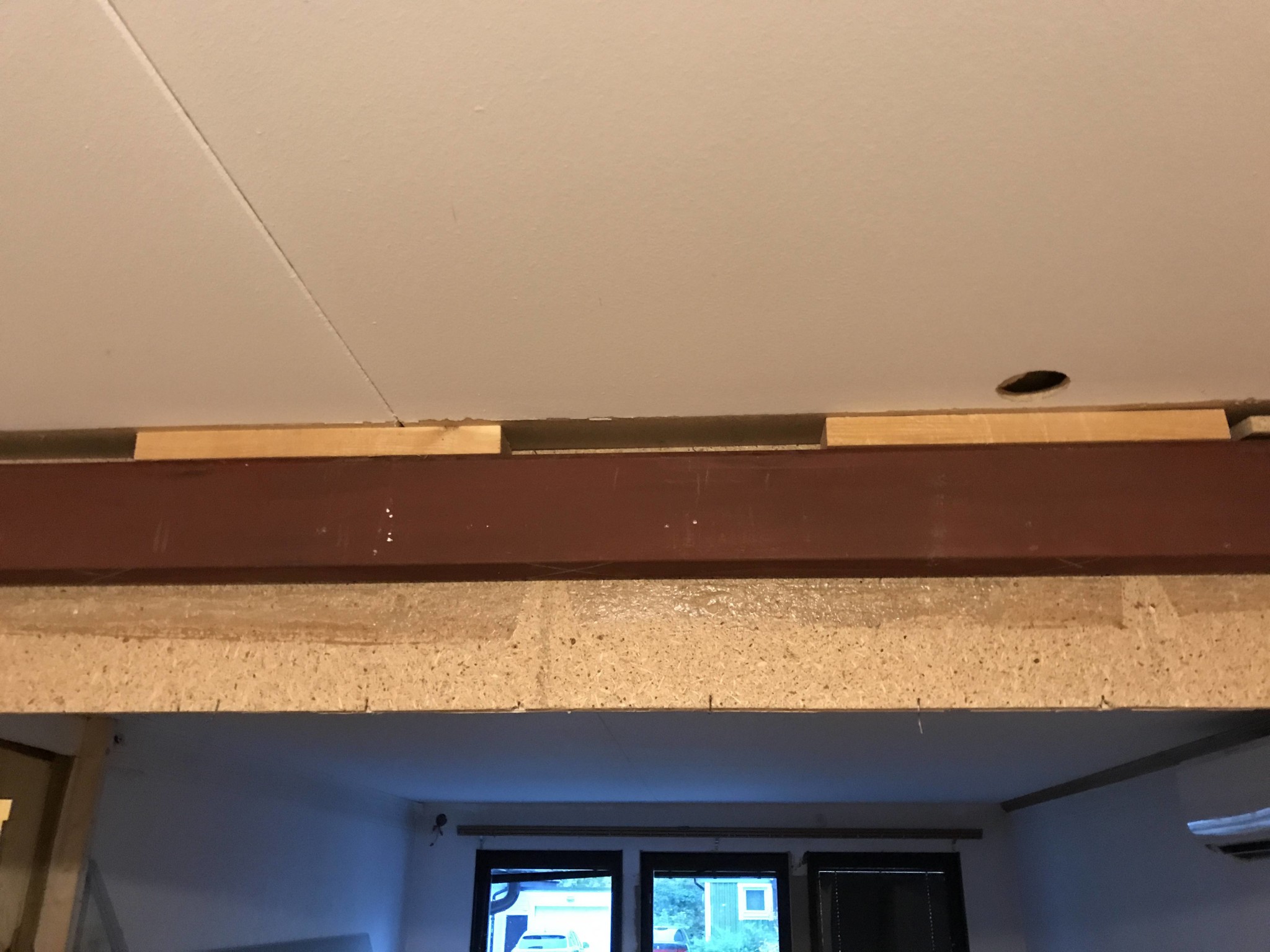
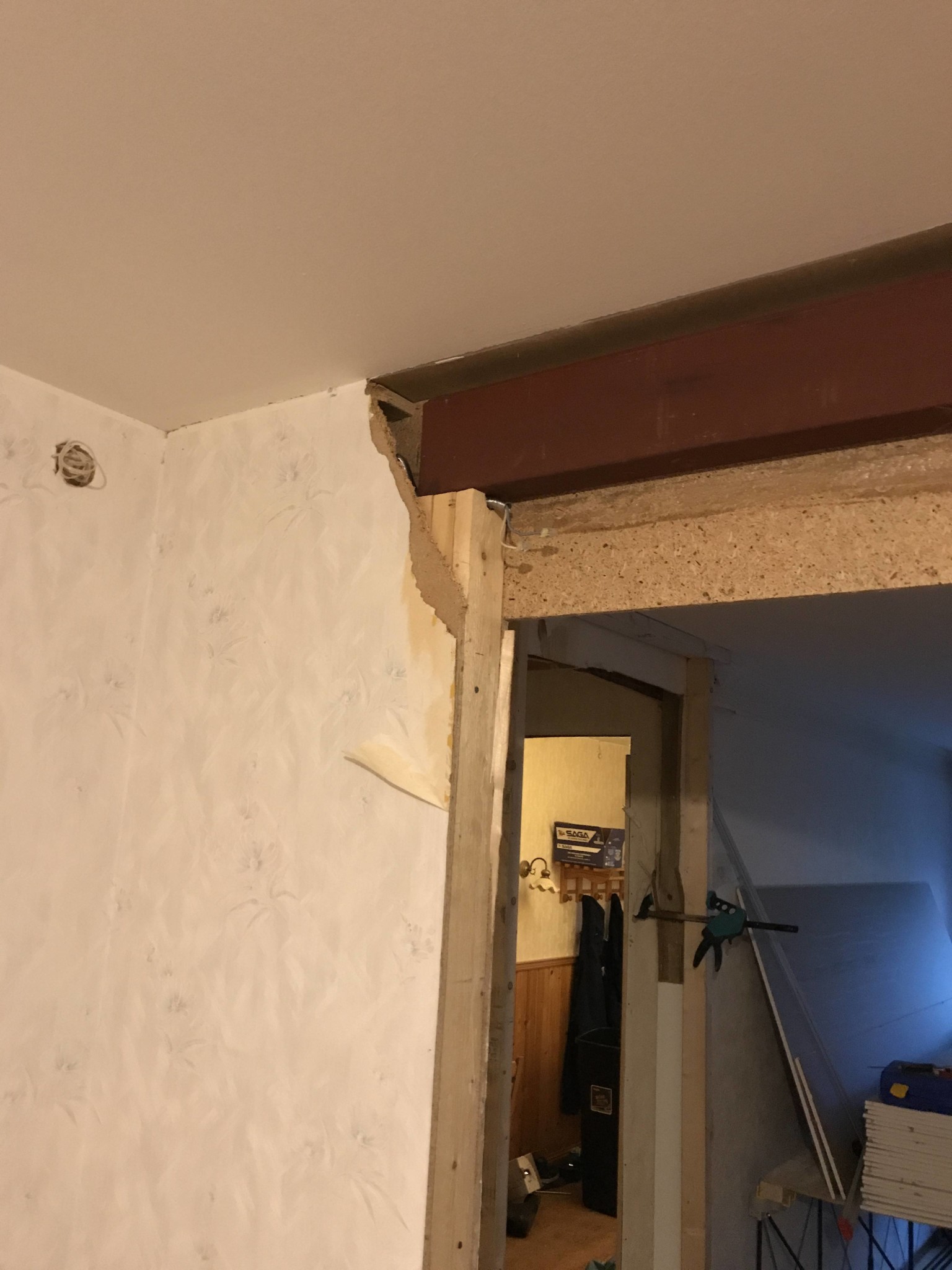
In 1982, parts of the wall seem to have been taken down and opened up, and the wall was supported with this beam
I seem to recall that this was the information I provided at the building supply store.
It is not possible to make such comparisons without knowing what should be dimensioning, the ultimate limit or the serviceability limit (i.e., deflection). Glulam and steel have completely different properties in these respects. A glulam beam of 115x315 can handle a maximum moment of about 40 kNm. With a span of 3 m, this corresponds to a uniformly distributed load of about 3600 kg/m. With this load, the glulam beam can also keep the deflection under 10 mm. To handle the load, an HEA 140 is sufficient, but to handle the deflection, an HEA 180 is required. However, I would like to question whether the person helping you has really calculated correctly. 115x315 over 3 meters are quite substantial dimensions.
Guess the person who calculated wanted both belt and suspenders.
The beam should support half of the floor above as well as the self-weight of the wall above, but probably no roof load. The maximum deflection is the determining factor since the floor above is affected. Roughly calculated, I conclude that a glulam beam of 115x225 should suffice. You can reduce the beam height by choosing a wider beam. For a more precise calculation, a dimensioned sectional drawing is needed. I think you should skip the idea of a steel beam. You gain almost nothing from it and everything just becomes more complicated.
The beam should support half of the floor above and the weight of the wall above, but probably no roof load. The maximum deflection is the determining factor since the floor above is affected. Roughly calculated, I estimate that a glulam beam that is 115x225 should suffice. You can reduce the beam height by choosing a wider beam. For a more precise calculation, a dimensioned sectional drawing is needed. I think you should abandon the idea of a steel beam. You gain almost nothing from it and everything just becomes more complicated.
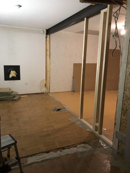
I managed to get an I140 beam for a really good price and don't think it's particularly difficult to put it in place. I had a friend over who has supported his own walls and he "thought" an I120 beam would be sufficient.
What do you mean by I140? If it's an IPE 140, it won't be sufficient. You need to go up to IPE 160. With double plasterboard as fire insulation, you're up to a height of at least 183 mm.
Is the beam just resting loosely on the joists? As it looks now, there's nothing guiding the beam or its bearings laterally. The downside of IPE beams is that they are prone to tipping (probably not decisive in your case). I suggest you brace the upper flange along the entire beam on both sides, for example with angle irons that you screw into the ceiling joists and press against the upper flange.
Vi vill skicka notiser för ämnen du bevakar och händelser som berör dig.