I need help interpreting a construction drawing to find the load-bearing interior walls.
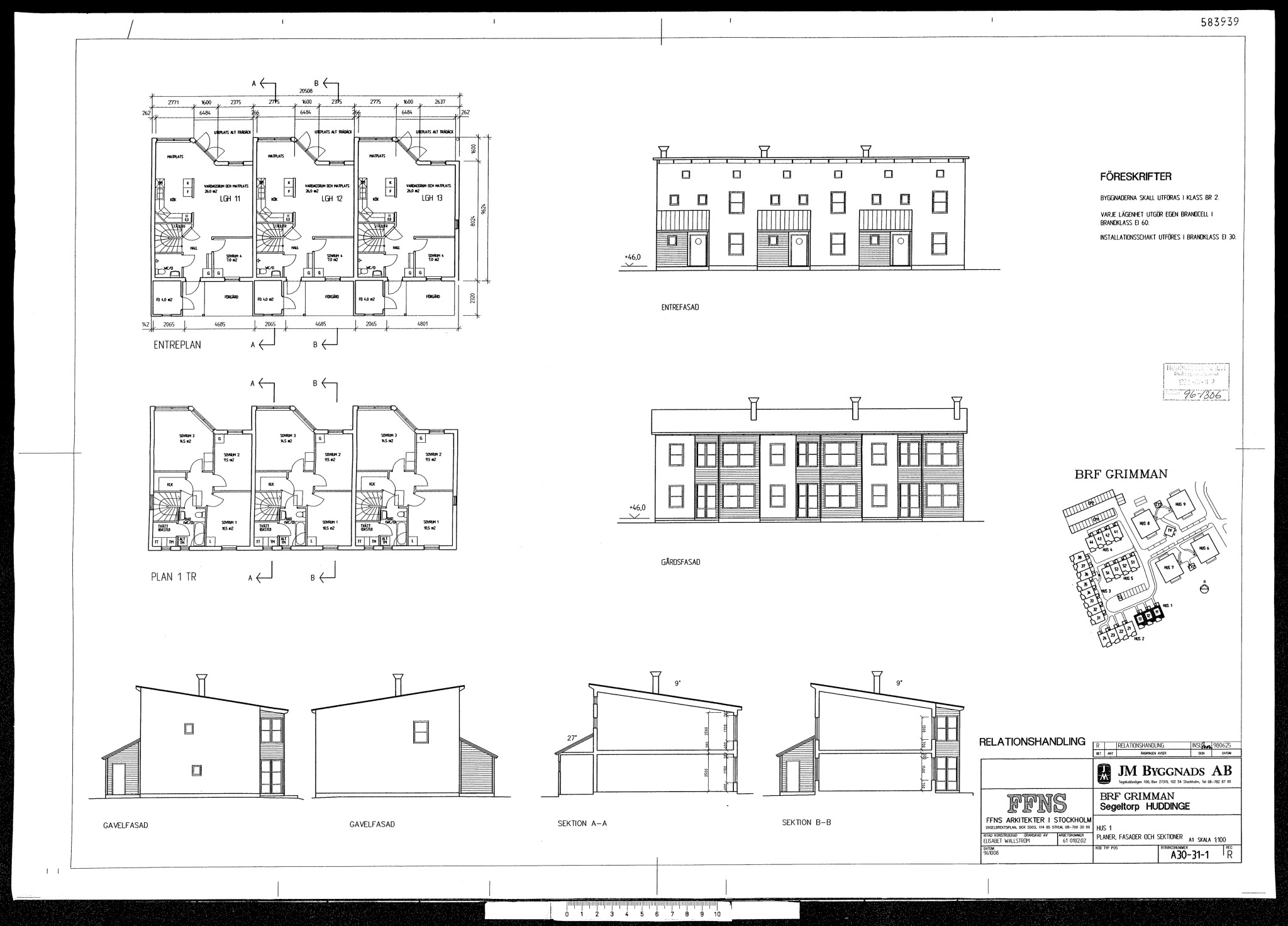
This is the ground floor of a 2-story townhouse. Built in wood, the joists between the floors are constructed with 220mm beams spanning from outer wall to inner wall, resulting in a length of 6500mm.
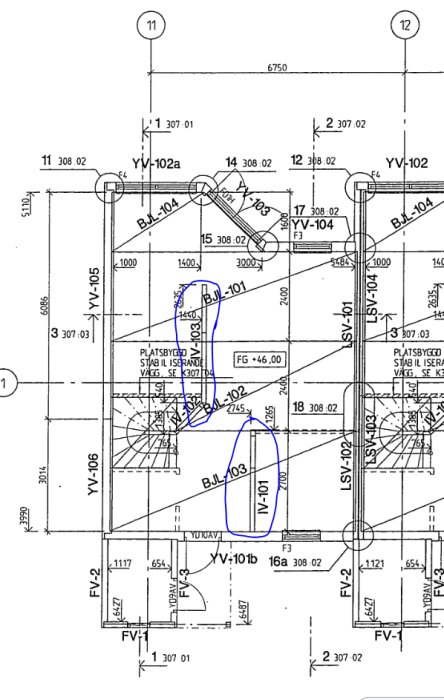
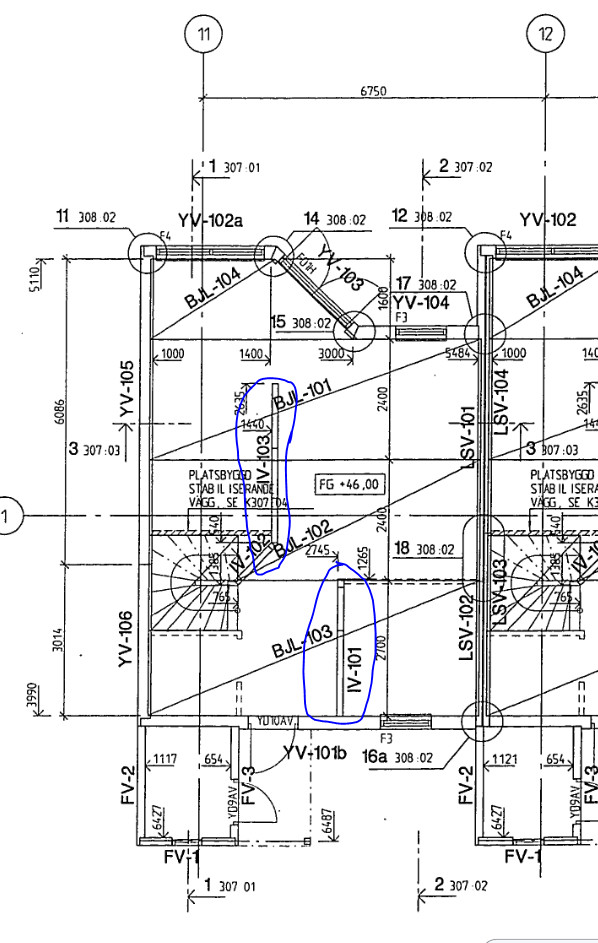
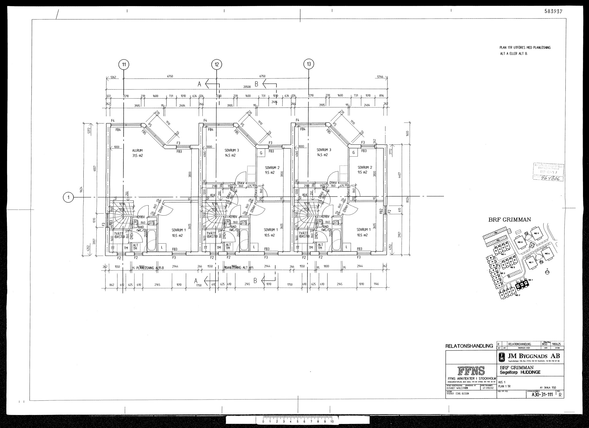
My guess is that IV-101 and IV-102 and IV-103 are load-bearing for the construction as they are marked and solid-lined, while the other interior walls are dashed.
These walls are built with wooden studs and are about 120mm thick, whereas the other walls are metal studs.
There is also a site-built stabilizing wall by the stairs that runs from the concrete slab all the way up to the roof structure.
We want to demolish IV-103 to open up the space and probably need to replace it with a beam and post.
If anyone has suggestions for a contractor in the Stockholm area, I would gladly welcome that to move forward.
You might have to upload some more drawings if we're going to understand how the house is built. Preferably if you have detailed drawings of e.g. BJL-103 (bjälklag 103). The house is prefab constructed in some way.
You'll probably need to upload a few more drawings if you want people to understand how the house is built. Preferably if you have detailed drawings like BJL-103 (floor structure 103). The house is built in some sort of modular way.
If I had more drawings and information, I would have uploaded it of course. Unfortunately, I don't have any more drawings of the construction that provide more information than this one.
What is the house supplier called? House model? Year of construction?
Unfortunately, I don't have much more information, we only moved here a year ago, have searched for documents in Huddinge's building permit archive where I found the above drawing among others but not much else useful.
I know it was built by JM starting in 1997.
I guess I'll have to find an engineer who can help.
Without more drawings, unfortunately, there's probably no point in hiring an engineer unless you're prepared to tear down parts of the house. Ask your neighbors what they have.
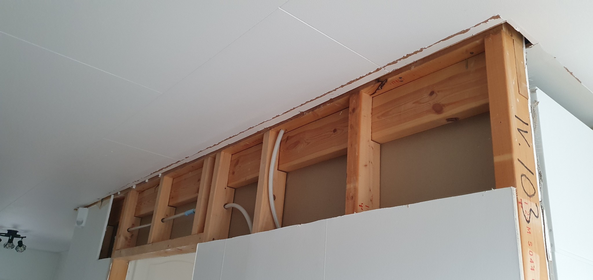
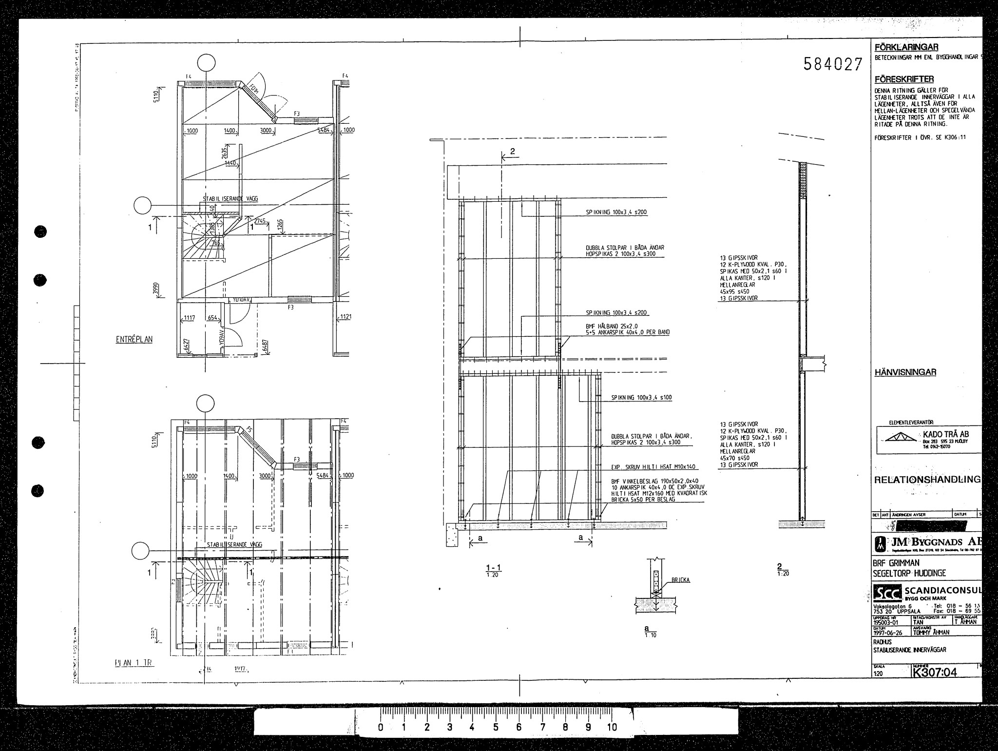
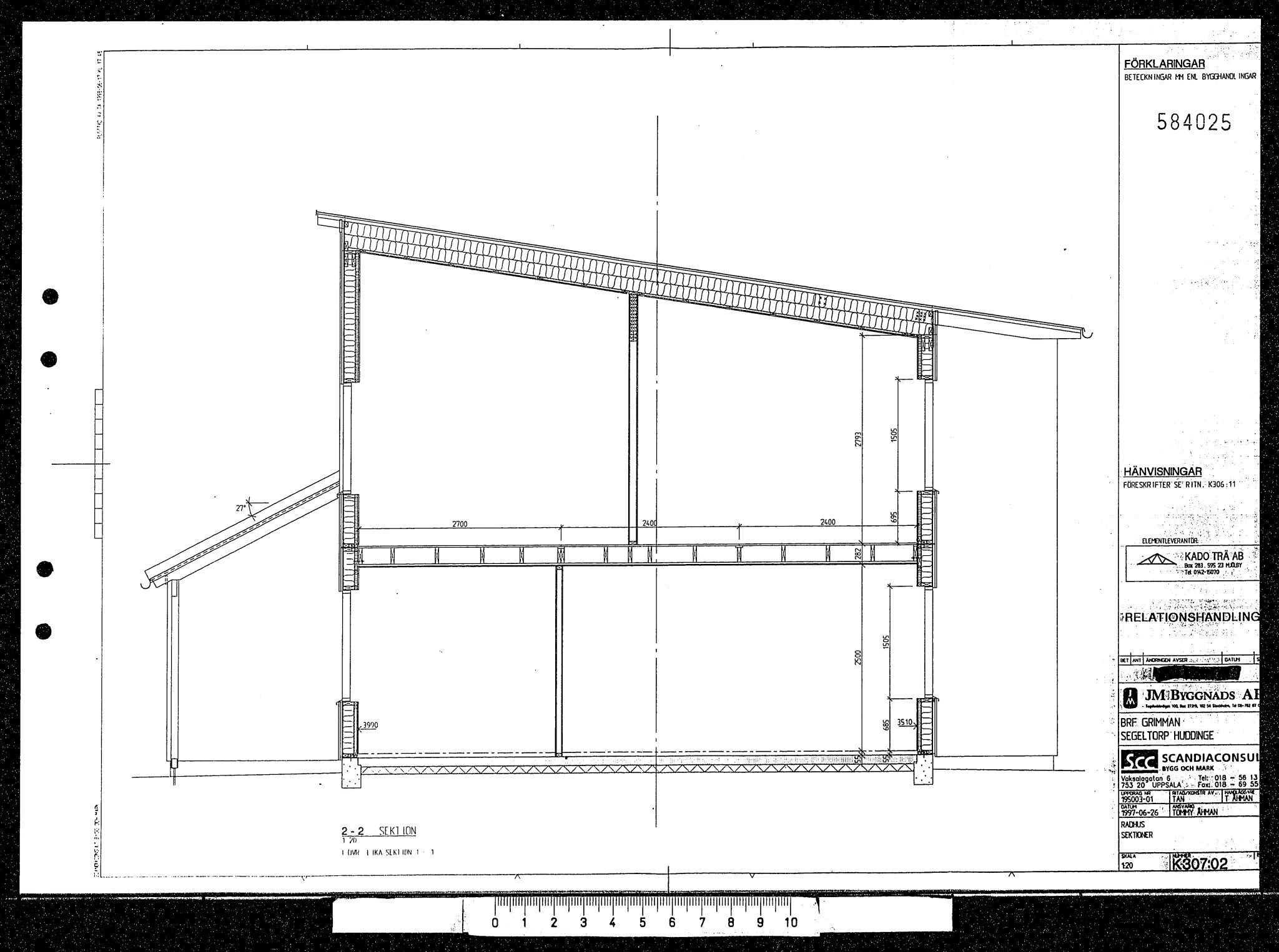
After a few months, I've made some progress and obtained some more construction drawings, although I'm not sure if they're helpful. I've also opened up the wall that will be demolished to see how it's constructed.
Attaching images here.
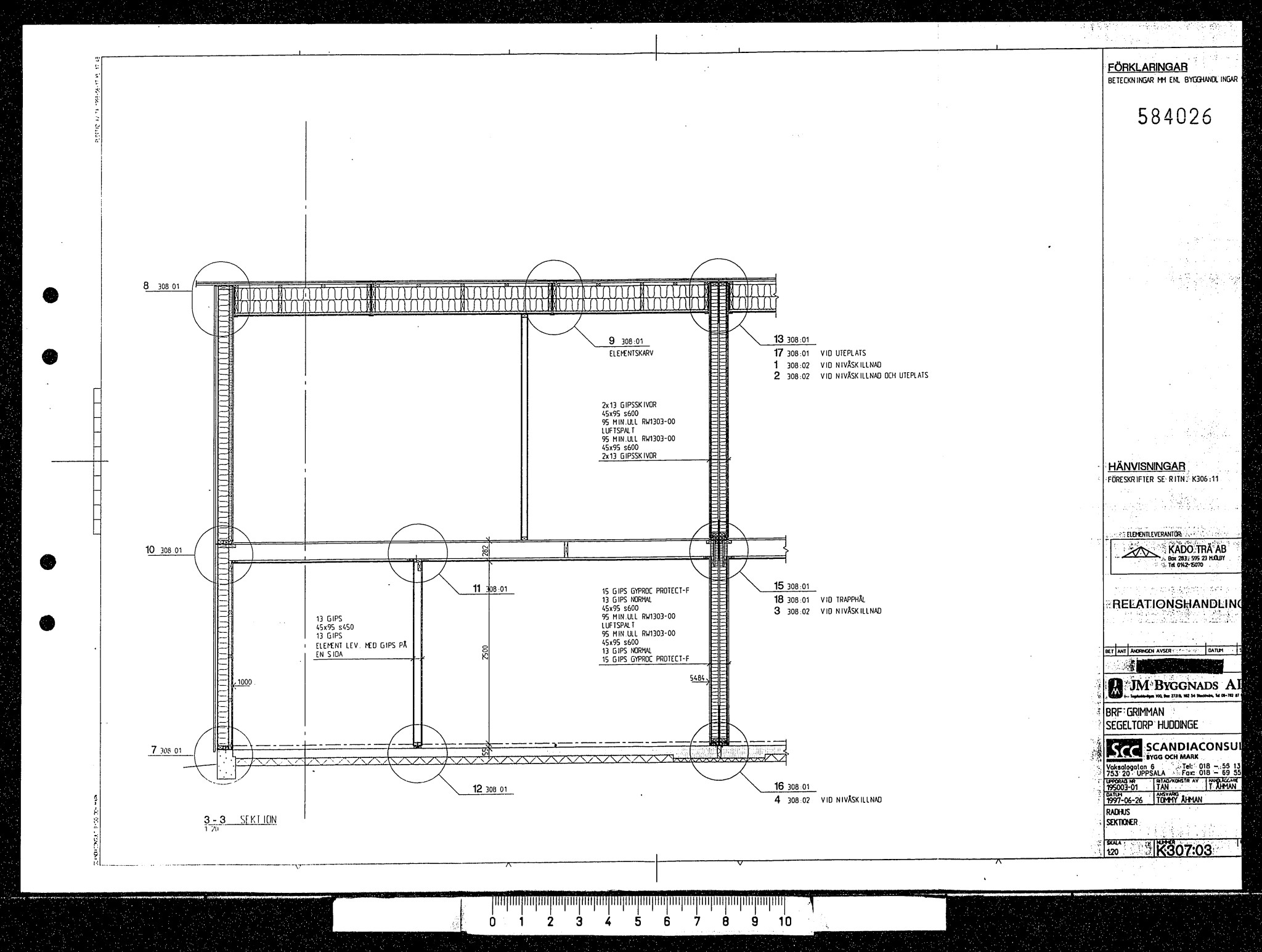
The floor between the levels is 200mm and seems to have a spacing of cc400.
Is there any more information that could be useful for further calculations on this?
Without more blueprints, it's probably unfortunately pointless to hire an engineer, unless you're prepared to tear down parts of the house. Ask your neighbors what they have.
Now that I've added a bit more information about the wall and the beam, do you have any wise advice to offer then? =)
After a few months, I have made some progress and obtained some more construction drawings, though I'm not sure if they will be of any help. I have also opened up the wall that is to be demolished to see how it is constructed.
Attaching pictures here.
The floor structure between the floors is 200mm and seems to be placed at cc400.
Is there any more information that could be useful to calculate more on this?
Your construction drawings attached in #7 are quite "empty".
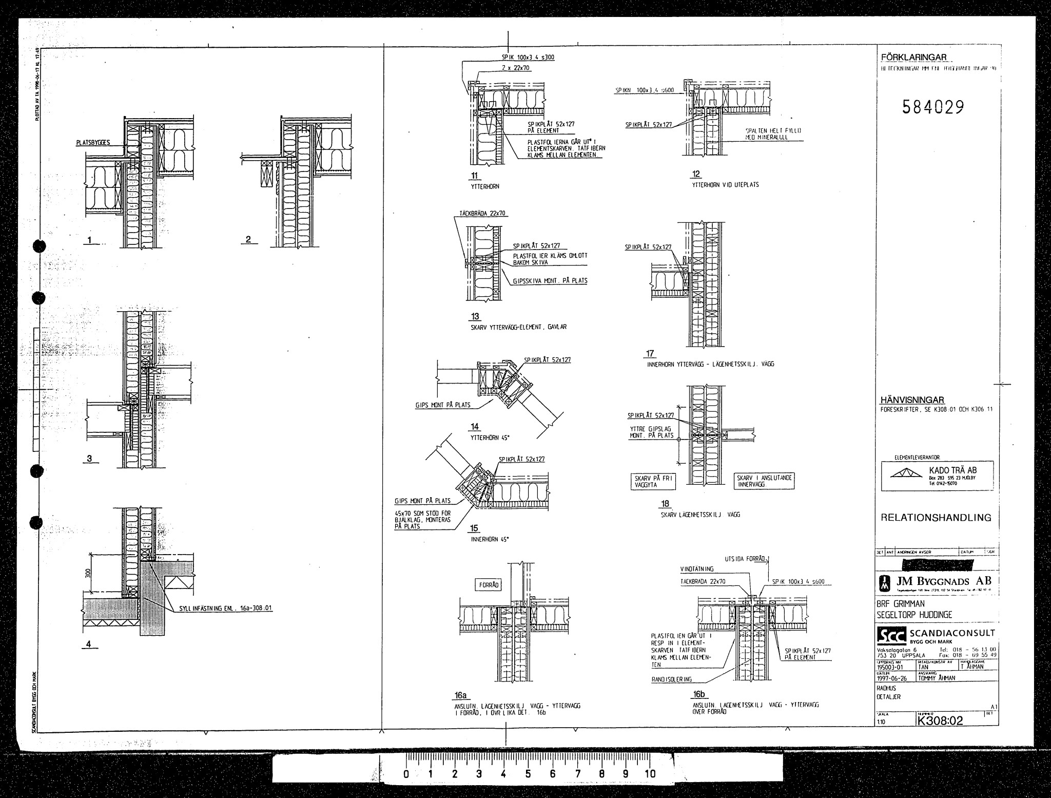
The recessed beam under the wall plate is there to distribute forces from above and should be a strong indication that the wall is intended to be load-bearing.
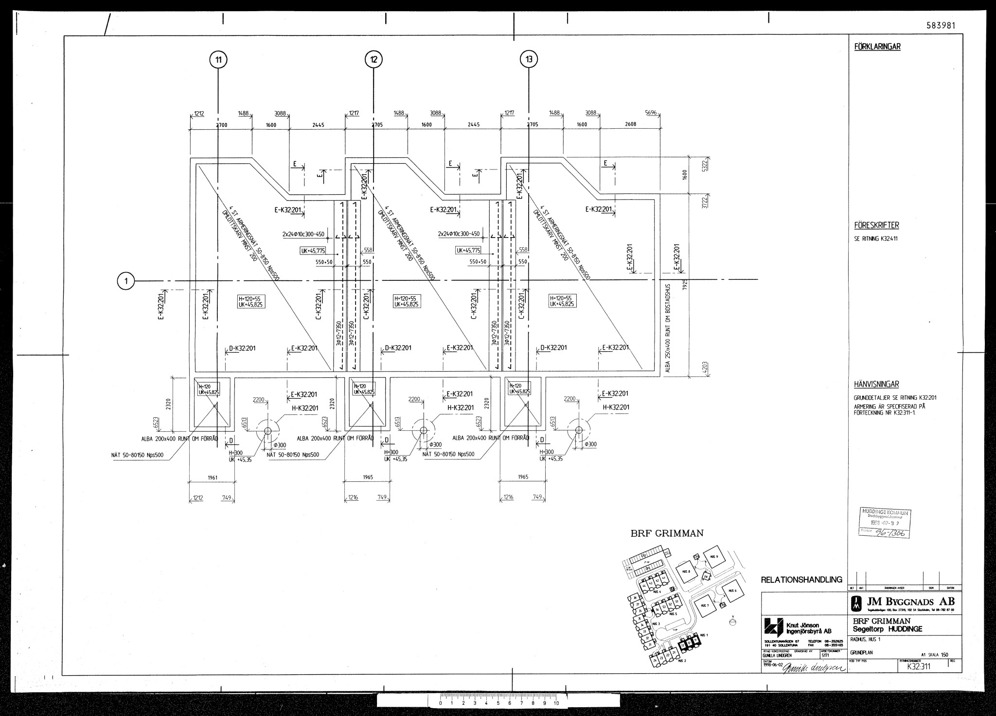
The drawings support the assumption that IV-101 (inner wall 101) cannot be removed. The house is a prefab construction, and the intermediate floor consists of three cassettes that need support in the middle. Everything is quite sophistically calculated, so I advise against experimenting.
The drawings support the assumption that IV-101 (inner wall 101) cannot be removed. The house is a prefab construction and the mid-floor consists of three cassettes that need support in the middle. Everything is quite sophisticatedly calculated, so I advise against experiments.
Isn't it IV-103 they want to remove? See the first picture in post #7.
But that one is probably load-bearing as well.
The drawings support the assumption that IV-101 (inner wall 101) cannot be removed. The house is a panel construction, and the intermediate floor consists of three cassettes that need support in the middle. Everything is quite sophisticatedly calculated so I advise against experimenting.
KKane said:
Isn't it IV-103 they want to remove? See the first image in post #7. But it is also load-bearing.
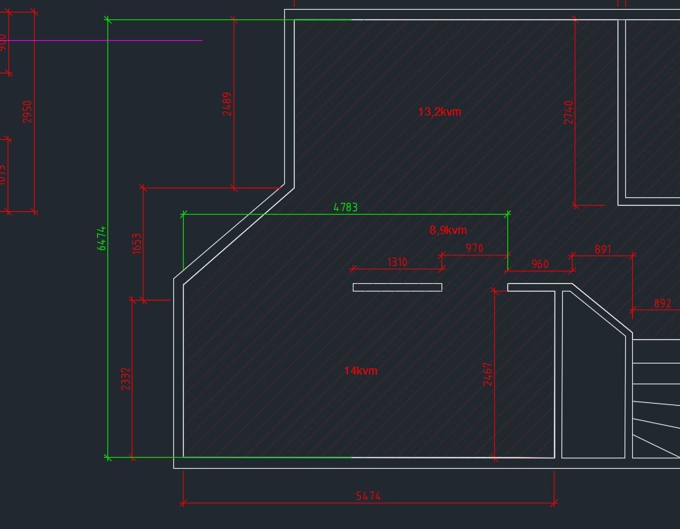
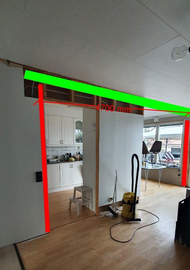
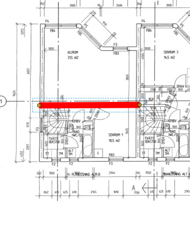
Thank you for your answers, it's correct that it's IV-103 we want to remove and have come to the same conclusion as you that it is load-bearing in the construction. So now the question is about the possibility of replacing it with posts at each end. Red= post and green = Beam.
As I understand it, it's only weight from the intermediate floor that loads this wall. Load from the roof is absorbed by a laminated beam that distributes to the outer wall and the wall to the next townhouse. Red line below is from the upper floor.
I arrive at a smaller deformation with 90x405 than your calculation shows. But 90x405 is an impossible dimension in this context. You can replace it with 140x360 or 190x315. A 90x90 column is sufficient from a load-bearing perspective, but the columns should have a common width measurement with the beam. You need to check with the detailed sections through the base plate that the columns are positioned correctly so that there's reinforcement to absorb the column loads.
Vi vill skicka notiser för ämnen du bevakar och händelser som berör dig.