6,855 views ·
24 replies
7k views
24 replies
Calculation help for sizing H-beam.
Hello
I am about to open up a load-bearing wall and need some help from someone here who is knowledgeable about designing the necessary supporting beam. If this is your specialty, you have a wonderful opportunity to gather lots of good karma...for future use.") I am attaching drawings I made to the best of my ability. This doesn't necessarily mean they contain even a fraction of the information needed to make the calculations, but please don't give up over such a trivial matter - I am more than happy to answer all questions, I built the house myself and know more or less where every nail is placed.
I am attaching drawings I made to the best of my ability. This doesn't necessarily mean they contain even a fraction of the information needed to make the calculations, but please don't give up over such a trivial matter - I am more than happy to answer all questions, I built the house myself and know more or less where every nail is placed.
Some conditions.
The foundation will hold, as Leca engineers have promised me, so we can leave that aside. The house is located on a height in Björlanda, Gothenburg. The distance to the sea is less than 1 km, so the snow zone should be low and the wind zone, if there is one, should be high.
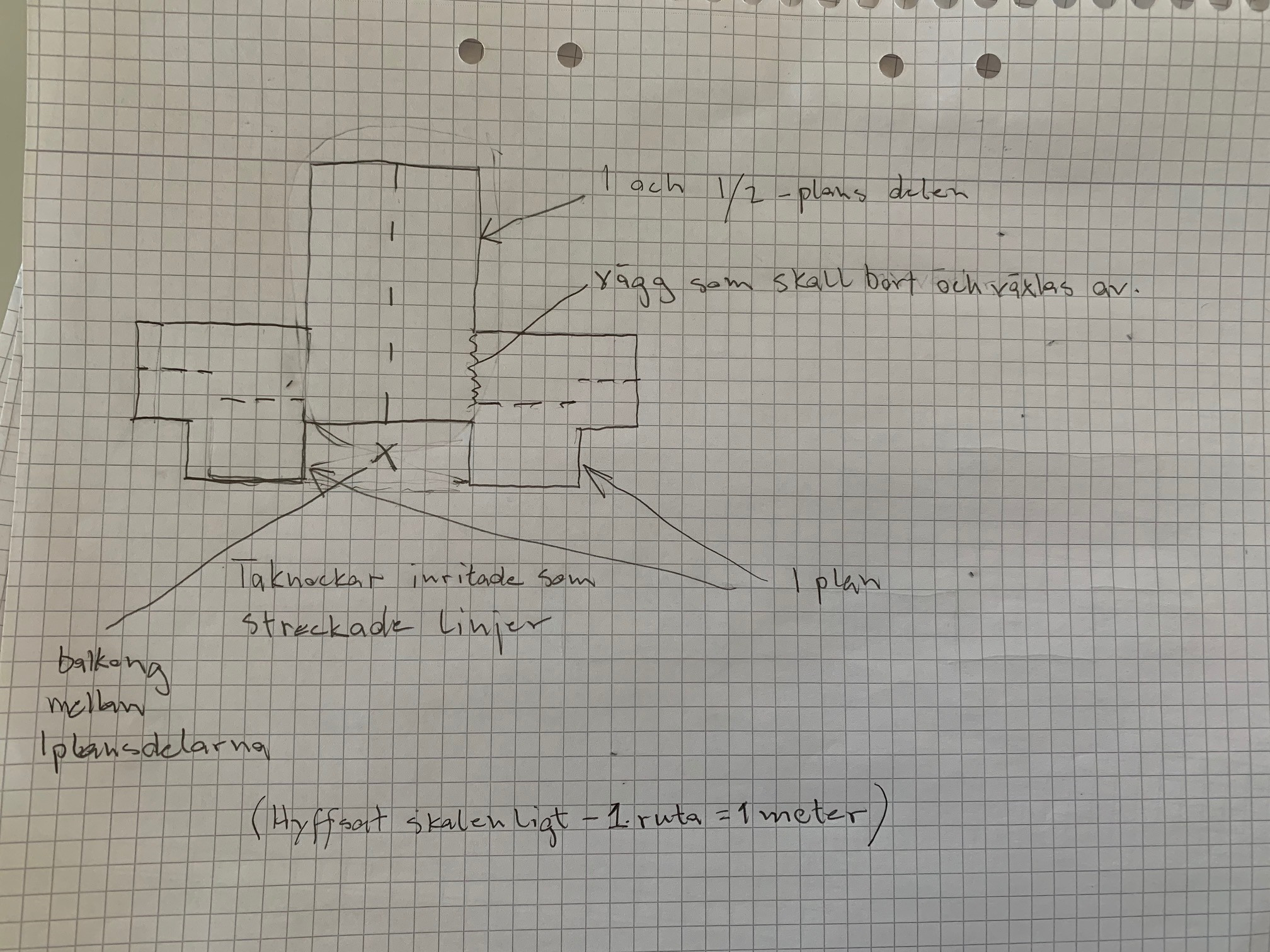
My house consists of three "free-standing" building sections. It has a central section with 1 and 1/2 floors. On each long side, it is joined by a one-story section. The one-story sections carry their own roof with truss rafters, so we can almost certainly leave them out of the calculations. Possibly some load might be transferred to the central part as the inner rafter of the one-story section is nailed to the wall of the 1 and 1/2 floor section.
The kitchen is located in one of the one-story sections - on the other side of the wall, that is in the 1 and 1/2 floor section, will be the dining/living room. I want to open up the wall between the kitchen and the dining/living room with a 3600 mm wide opening. It is the loads above this opening that need to be supported by the beam.
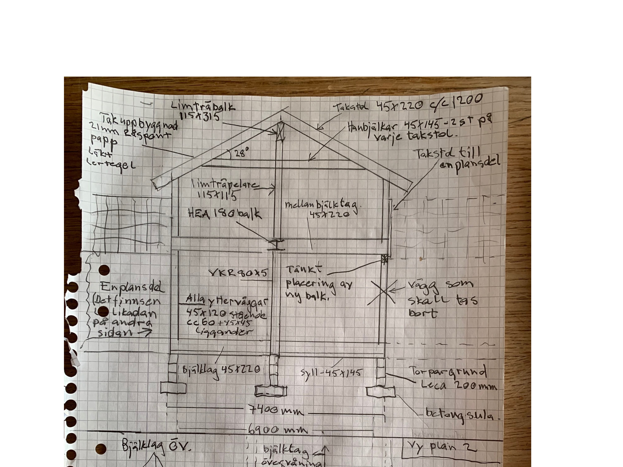
Dimensions of the 1 and 1/2 floor section.
7400x10800.
External walls are a total of about 250 mm thick, so the internal dimensions between the bearing studs are about 6900x10300 mm.
In the center of the house, there is an HEA180 beam supported by square profiles that I believe are called VKR 80x5 mm and act as the load-bearing wall, so to speak.
All "external walls" are constructed as follows:
13 mm plasterboard
45x120 mm vertical stud
45x45 mm horizontal stud
9 mm exterior plasterboard
battens
vertical cladding with 21 mm wide boards.
Construction of the 1 and 1/2 floor section from bottom to top is:
Crawl space foundation with Lecablocks on concrete footing.
45x145 mm sill in pressure-treated wood.
45x220 mm floor joists spaced at 600 mm.
First-floor wall: 45x120 mm vertical studs spaced at 600 mm with 45x120 mm top and bottom plates - total wall height 2480 mm.
45x220 mm joist floor on the upper floor spaced at 600 mm.
Second-floor wall: 45x120 mm vertical studs spaced at 600 mm with 45x120 mm top and bottom plates - total wall height 2070 mm.
The roof:
Roof pitch of 28 degrees.
Roof construction from bottom to top:
13mm plasterboard
45x70
45x220
21 mm rough boards
roofing felt
battens
Vittinge clay tiles.
Trusses spaced at 1200 mm with 250 mm sprayed loose insulation to the ridge.
Other weights to consider.
Weights from the upper floor joists apart from their own weight, I assess as relatively low. It is (as I hope is evident from the drawing) partially open between the floors. Where there is flooring, there is a large sofa group where up to 15 average-weight Swedes might sit and might engage in synchronized jumping while watching, for example, the pole vault final in the Olympics. No, that's not true, only 5-6 of them will load the beam, the rest are situated beyond it. There are no bathrooms, etc., that are sensitive to minor movements on this side of the upper floor at all.
Many thanks in advance - May Shiva reincarnate you into exactly what you wish...//Håkan
I am about to open up a load-bearing wall and need some help from someone here who is knowledgeable about designing the necessary supporting beam. If this is your specialty, you have a wonderful opportunity to gather lots of good karma...for future use.
I am attaching drawings I made to the best of my ability. This doesn't necessarily mean they contain even a fraction of the information needed to make the calculations, but please don't give up over such a trivial matter - I am more than happy to answer all questions, I built the house myself and know more or less where every nail is placed.Some conditions.
The foundation will hold, as Leca engineers have promised me, so we can leave that aside. The house is located on a height in Björlanda, Gothenburg. The distance to the sea is less than 1 km, so the snow zone should be low and the wind zone, if there is one, should be high.
My house consists of three "free-standing" building sections. It has a central section with 1 and 1/2 floors. On each long side, it is joined by a one-story section. The one-story sections carry their own roof with truss rafters, so we can almost certainly leave them out of the calculations. Possibly some load might be transferred to the central part as the inner rafter of the one-story section is nailed to the wall of the 1 and 1/2 floor section.
The kitchen is located in one of the one-story sections - on the other side of the wall, that is in the 1 and 1/2 floor section, will be the dining/living room. I want to open up the wall between the kitchen and the dining/living room with a 3600 mm wide opening. It is the loads above this opening that need to be supported by the beam.
Dimensions of the 1 and 1/2 floor section.
7400x10800.
External walls are a total of about 250 mm thick, so the internal dimensions between the bearing studs are about 6900x10300 mm.
In the center of the house, there is an HEA180 beam supported by square profiles that I believe are called VKR 80x5 mm and act as the load-bearing wall, so to speak.
All "external walls" are constructed as follows:
13 mm plasterboard
45x120 mm vertical stud
45x45 mm horizontal stud
9 mm exterior plasterboard
battens
vertical cladding with 21 mm wide boards.
Construction of the 1 and 1/2 floor section from bottom to top is:
Crawl space foundation with Lecablocks on concrete footing.
45x145 mm sill in pressure-treated wood.
45x220 mm floor joists spaced at 600 mm.
First-floor wall: 45x120 mm vertical studs spaced at 600 mm with 45x120 mm top and bottom plates - total wall height 2480 mm.
45x220 mm joist floor on the upper floor spaced at 600 mm.
Second-floor wall: 45x120 mm vertical studs spaced at 600 mm with 45x120 mm top and bottom plates - total wall height 2070 mm.
The roof:
Roof pitch of 28 degrees.
Roof construction from bottom to top:
13mm plasterboard
45x70
45x220
21 mm rough boards
roofing felt
battens
Vittinge clay tiles.
Trusses spaced at 1200 mm with 250 mm sprayed loose insulation to the ridge.
Other weights to consider.
Weights from the upper floor joists apart from their own weight, I assess as relatively low. It is (as I hope is evident from the drawing) partially open between the floors. Where there is flooring, there is a large sofa group where up to 15 average-weight Swedes might sit and might engage in synchronized jumping while watching, for example, the pole vault final in the Olympics. No, that's not true, only 5-6 of them will load the beam, the rest are situated beyond it. There are no bathrooms, etc., that are sensitive to minor movements on this side of the upper floor at all.
Many thanks in advance - May Shiva reincarnate you into exactly what you wish...//Håkan


Roughly, it is at least about a HEA 180.
Thank you for the response. That was what I was afraid of. To be able to build it into the wall, I preferably don't want anything wider than 140 mm. I assume an HEB140 isn't enough, but perhaps an I-beam or maybe a square profile of 140x??? mm could be an alternative. If not, I can consider reducing the opening somewhat - so the conditions would be like this - as large an opening as possible but with a maximum 140 mm wide beam.
I missed some measurements and info that you might have figured out yourself, but just to be safe:
The span between the center of the existing HEA180 beam (middle of the building) and the wall to be supported is about 3420 mm.
Of course, the measurement will be the same between the glulam beam's center in the roof ridge and the outer wall on the upper floor.
The roof overhang is 500 mm.
The loads to be supported by the beam will be:
From three floor joists on the upper floor - cc600.
and
3 and 1/2? roof trusses cc 1200 (The vertical load from roof truss number 3 lands 50 cm in on the beam - so I don't know how to calculate there since the loads from roof truss number four will continue to go down into the existing wall.
If it is important for the calculation, I will list where on the beam above the loads theoretically fall from where the beam's support nearest the gable is. (That is, the short side of the house + 500 mm since the wall that supports the beam is 500 long - see sketch)
Floor joist 1 - 2000 mm
Floor joist 2 - 2600 mm
Floor joist 3 - 3200 mm
Roof truss 1 - 700 mm
Roof truss 2 - 1900 mm
Roof truss 3 - 3100 mm
Hmmm, this is tricky.... I barely understand myself what I mean despite trying to be as clear as I can
An HEA180 corresponds to the following profiles.
HEB160
HEM140
VKR200x100x10
Reducing the span slightly is very advantageous.
What is the reason for the beam being 4.6m but the opening 3.6m?
If I interpret your sketches correctly, only half of the beam supports the floor, and the other half is open between the floors?
HEB160
HEM140
VKR200x100x10
Reducing the span slightly is very advantageous.
What is the reason for the beam being 4.6m but the opening 3.6m?
If I interpret your sketches correctly, only half of the beam supports the floor, and the other half is open between the floors?
Last edited:
Hello
Thanks for the info.
It was mainly that I don't know what should be in place to support the beam as I have 500 mm as a maximum, so to speak. If, for example, 3 screwed together 45x120 on each side is enough, then the beam doesn't need to be longer than 3870 mm (3600+45x6).
Thanks for the info.
It was mainly that I don't know what should be in place to support the beam as I have 500 mm as a maximum, so to speak. If, for example, 3 screwed together 45x120 on each side is enough, then the beam doesn't need to be longer than 3870 mm (3600+45x6).
Did I understand the sketch correctly that the beam lies halfway where it is open between the floors?
Okay. Since the beam also needs to withstand wind load in this area, it should extend out and meet the gable to obtain horizontal support, or alternatively set up some form of column that reaches up to the roof to get horizontal support.
I mean that the truss from the single-story section, which is nailed together with the 1 and 1/2 story section, takes lateral forces in the wall. Also, the balcony helps too... but I'm just guessing, of course...
Ok, I thought it was a hole in the facade. If it's a building structure, the wind doesn't blow as much on the beam
Another option is limträ 140x360.