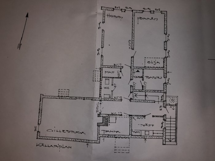
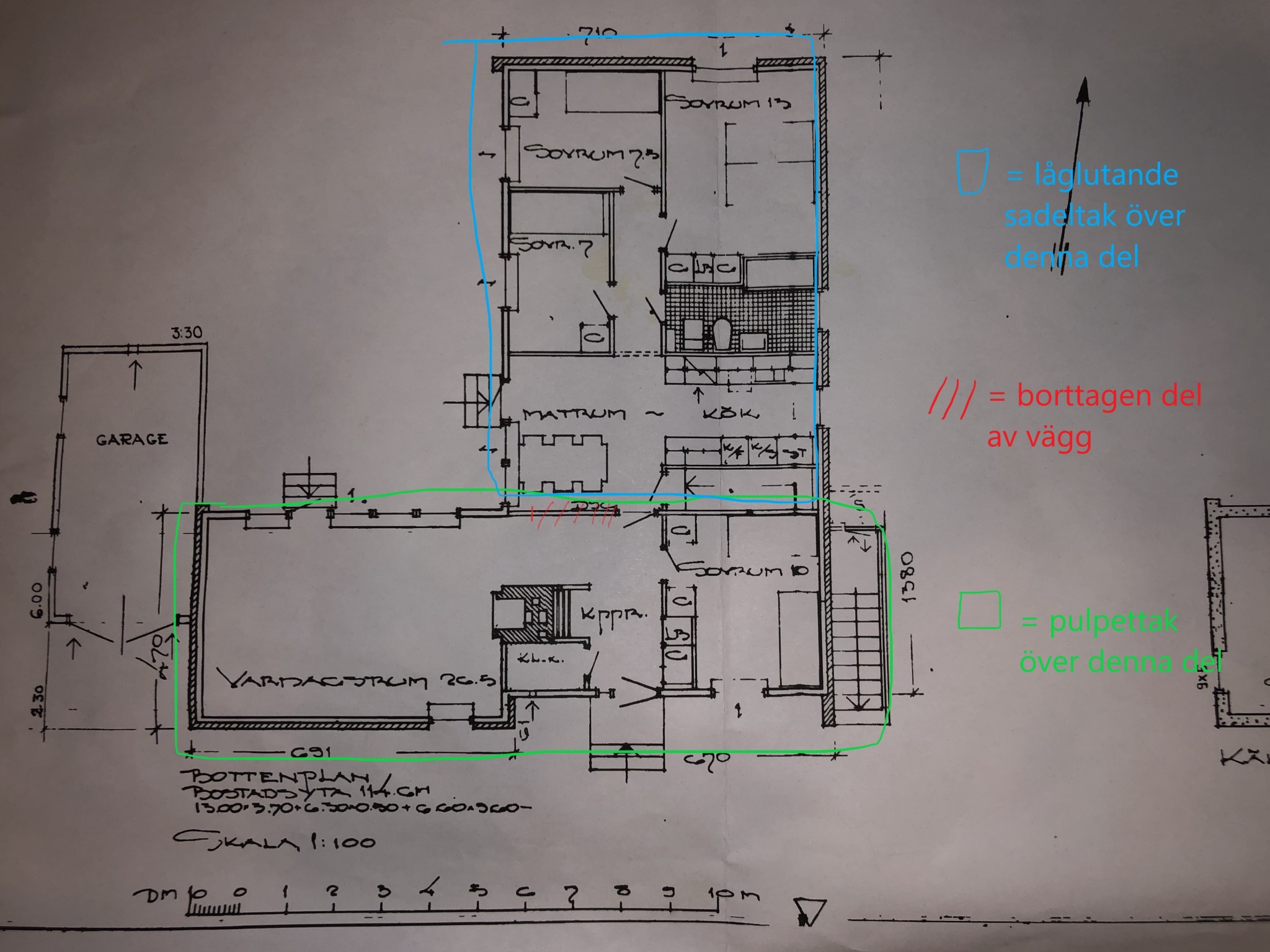
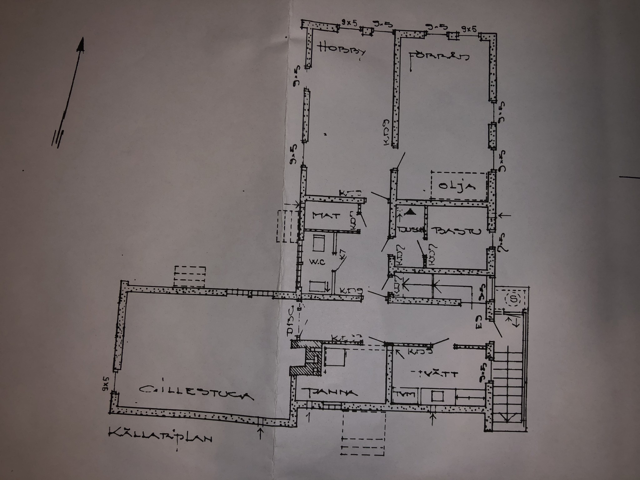
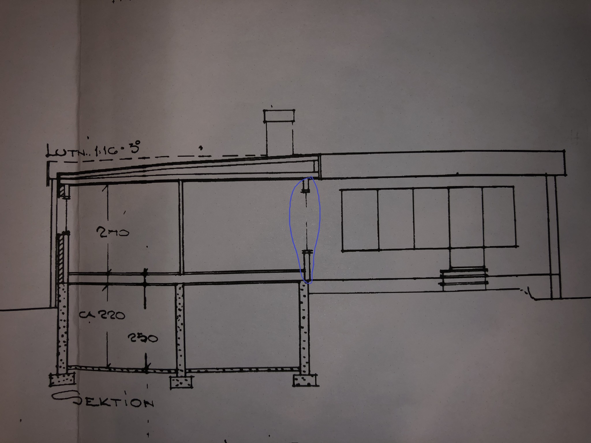
I thought I'd grace the forum with yet another "load-bearing wall question." I have a catalog house in an angle from Svenska Trähus AB built in '68, where previous owners have removed parts of the wall between the dining area and hall/living room (see drawing). I haven't really thought much about this before since there's still a "lowered" part which I assumed was a clad supporting beam. Now that we're renovating the kitchen and dining area, however, I suspect that this "lowered" part might just be a small leftover piece of the old wall without additional reinforcement, and in any case, it couldn't be wider than 45 mm Further demolition will soon answer how the construction is, but I thought I'd start by trying to figure out if the original wall was ever considered load-bearing (though I find it hard to believe it wouldn't be).
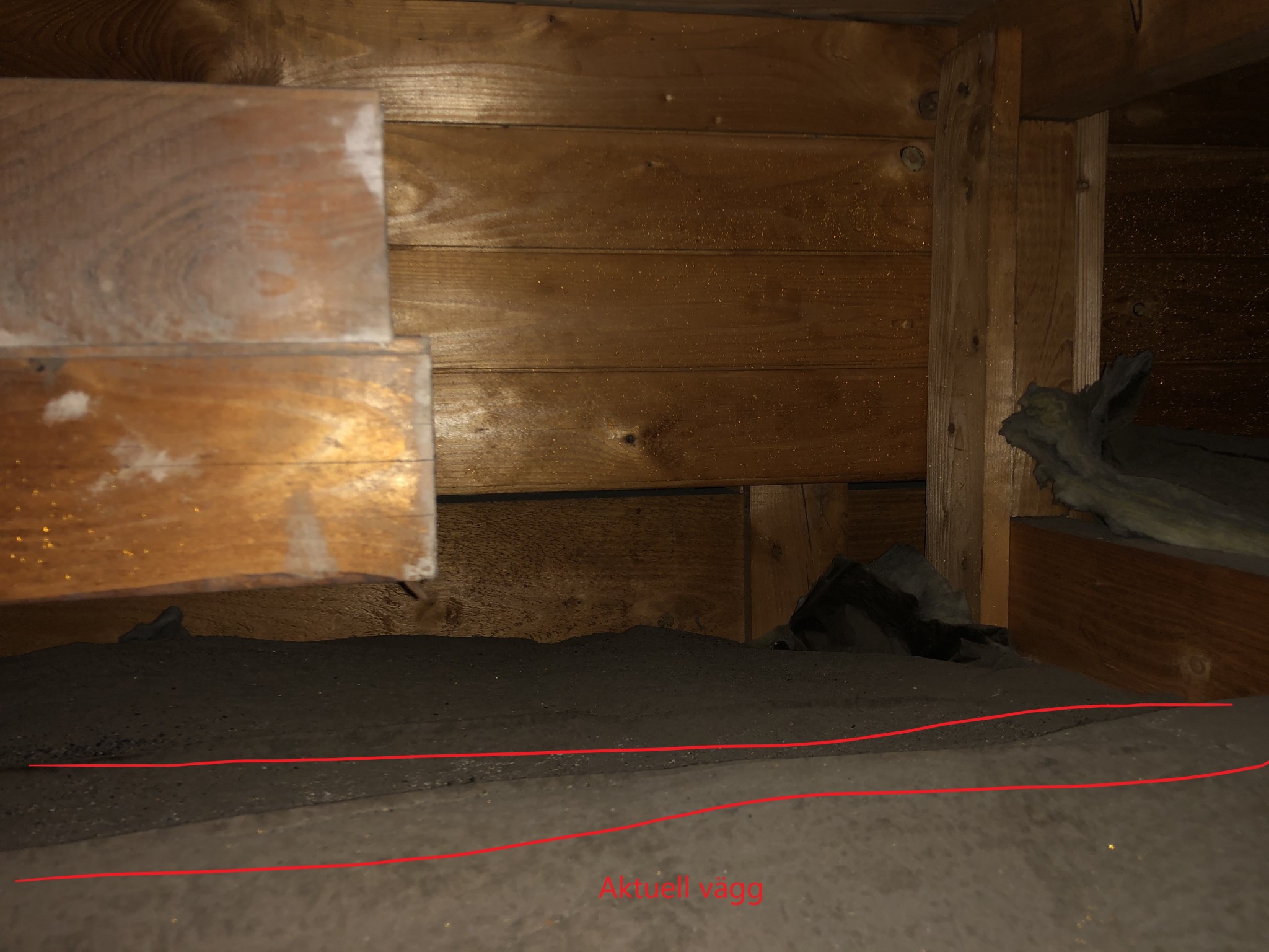
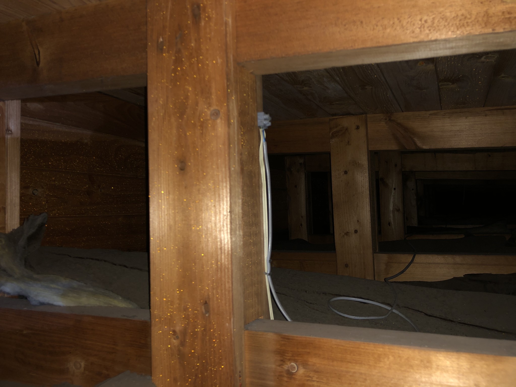
The wall in question is/was a direct continuation of the outer wall in the relevant body of the house, and the roof trusses (single-pitched roof) of course lie across the length of this part of the house (marked green on the drawing). The attached image is an attempt to photograph above the relevant wall, where it undeniably looks like the roof trusses rest on the current "wall remnant"? What does the expertise think? Should I be prepared in the renovation stages for needing a more substantial beam here?
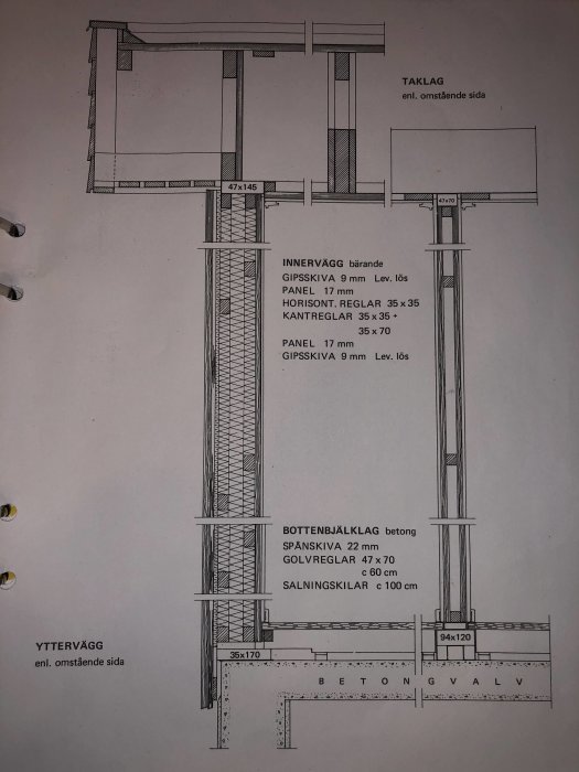
The wall is surely load-bearing for the trusses of the living room section. It should be replaced by a beam. Haven't you made an error concerning the roof types on the drawing? According to the sectional drawing, the bedroom section has a mono-pitched roof. However, this does not affect the question of the removed wall's status.
Thank you for the answer! That's what I suspected... I understand it's difficult to say exactly based on this information, but approximately what dimension of beam would you estimate it could be, so that I can make a reasonable assessment of the current state? The snow zone is 1.5, and as mentioned, it's a low-sloped roof construction surrounded by a parapet.
Regarding the roof construction, I haven't thought about it before, but the drawing actually doesn't match reality there. It's hard to see in the pictures from the attic, but it's obvious when standing on the roof. However, they don't seem to have followed these drawings too stringently in general, since the whole house is rotated 90 degrees on the plot compared to these, and the garage is placed at the short side of the bedroom section instead...
If you count on a span of 4 meters, a glued laminated beam with dimensions of 90x315 should be sufficient.
Looking at the section, it's clear that it's the bedroom part that is shown in cross-section. On the right, you can see the windows to the living room part. But it might not be built according to the drawing. I have over half a century of experience in reading blueprints. That's pretty hard to beat.
Since the entire wall has not been removed at this stage, the span between the supports is currently 2.5 m, but at least I have something to refer to. I will strip the existing construction this weekend and will try to remember to update here afterwards. Thanks for all the help so far!
Now I've managed to partially dismantle the construction, and although it seems to leave some to be desired, it wasn't as bad as I thought.
The current construction consists of a 220x45 C24 beam resting on supports made of three standing 45x70 beams (screwed together long side to long side) on each side. The span between the supports is 2.5 m.
The supports definitely need to be addressed as they are standing directly on the remnants of a now-removed tile floor and floor gypsum. Since I have good access for props under the beam, this should not be a major issue, but completely replacing the beam would be problematic without tearing down the surrounding ceiling.
However, I can spare an additional approximately 45 mm in width and about 100 mm in height. How far could I go in terms of structural strength with either an additional 220x45 glued and screwed to the existing one or a steel beam like IPE 100 or VKR-tube under the existing beam?
45x220 C 24 is on the weak side to handle maximum snow loads. A simple solution could be to screw-glue a 12 mm K-plywood board on each side of the beam. I see no need to involve steel. The posts should be brought down to the basement wall.
That would really be a practical solution - thank you very much for the idea!
The only question now is where I can get construction plywood in lengths over 2500 mm. The distance between the supports is indeed approximately 2500 mm, but including the part of the beam that rests on the supports, the total length is just over 2800 mm. I assume that any form of joint has a fairly drastic impact on the bending stiffness?
Yes, that sounds very reasonable now that you mention it - thank you so much for your answers! Then I'll buy K-plywood on my next trailer-equipped trip to the hardware store.
Click here to reply
Vi vill skicka notiser för ämnen du bevakar och händelser som berör dig.
 Further demolition will soon answer how the construction is, but I thought I'd start by trying to figure out if the original wall was ever considered load-bearing (though I find it hard to believe it wouldn't be).