18,493 views ·
18 replies
18k views
18 replies
Roof structure for longitudinal loft?
Hello everyone.
I am in the process of figuring out a construction solution that could work for my loft for a small timber-frame new build. The house's exterior dimensions are 6 by 11 meters with a raised wall height of 0.7 meters. Due to the small format, I would like to create space in the form of a longitudinal loft. Since I prefer to have it open to the ridge, I don't want any roof solution with a collar beam, and I would also like to avoid the support post that could be along one side (see side view). The roof beams could be 2 pieces of 45*220 beams laid on top of each other and nailed together at the ridge with nail plate, with a 45*195 ridge board on top of the rafters. The roof pitch is 45 degrees and will be clad with felt roofing (wooden roof). I would prefer to avoid a ridge beam (like a gabled roof) as the logistics become considerably more complicated when an 11-meter ridge beam needs to go out to an island, plus I don't want any support wall on the loft.
Now to my concern:
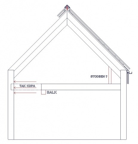
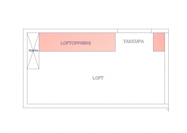
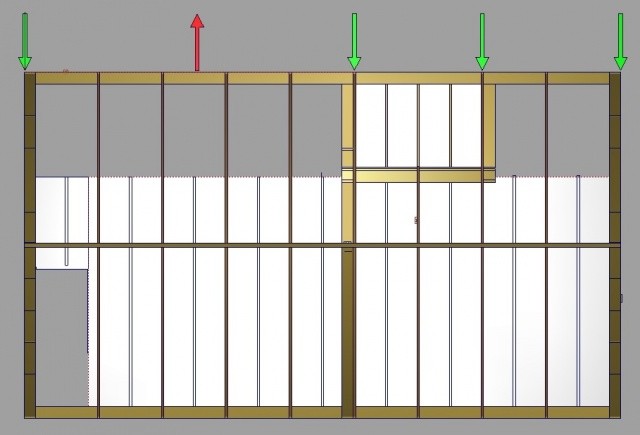
Is there a risk that the outer wall will be subjected to too much outward bowing according to the arrows? Or can this force be absorbed by the loft floor joists as seen in the top view? The dormer will be located between 3 rafters (cc1200), which means I have to cut and reinforce a rafter in the middle of the dormer. Does the raised wall height make the construction more difficult with more force on the outward bowing as a result? Is there another type of roof solution that could work with these conditions?
Gratefully accepting thoughts and solutions. Before I contact a structural engineer.
Image 1: Side view
Image 2: Plan view
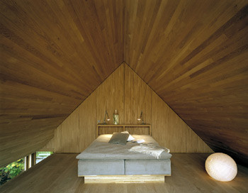
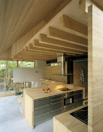
Image 3: Vineyard villa "The Mill House" where this solution exists.
I am in the process of figuring out a construction solution that could work for my loft for a small timber-frame new build. The house's exterior dimensions are 6 by 11 meters with a raised wall height of 0.7 meters. Due to the small format, I would like to create space in the form of a longitudinal loft. Since I prefer to have it open to the ridge, I don't want any roof solution with a collar beam, and I would also like to avoid the support post that could be along one side (see side view). The roof beams could be 2 pieces of 45*220 beams laid on top of each other and nailed together at the ridge with nail plate, with a 45*195 ridge board on top of the rafters. The roof pitch is 45 degrees and will be clad with felt roofing (wooden roof). I would prefer to avoid a ridge beam (like a gabled roof) as the logistics become considerably more complicated when an 11-meter ridge beam needs to go out to an island, plus I don't want any support wall on the loft.
Now to my concern:
Is there a risk that the outer wall will be subjected to too much outward bowing according to the arrows? Or can this force be absorbed by the loft floor joists as seen in the top view? The dormer will be located between 3 rafters (cc1200), which means I have to cut and reinforce a rafter in the middle of the dormer. Does the raised wall height make the construction more difficult with more force on the outward bowing as a result? Is there another type of roof solution that could work with these conditions?
Gratefully accepting thoughts and solutions. Before I contact a structural engineer.
Image 1: Side view
Image 2: Plan view
Image 3: Vineyard villa "The Mill House" where this solution exists.
As I see it, you have to think of the entire upper floor as a truss, which means that the floor must also be included in this calculation, just as you suggest with your arrows.
One solution could be to connect the outer walls with steel wires as tie rods right at the loft opening. Admittedly, they will be visible but it could even be a nice interior detail.
I don't think it's possible to create an 11 m long completely invisible roof structure. It fails at the loft opening.
An upper arm is probably the most common solution to this problem, but then you lose the design idea of a pointed inner roof ridge.
Thank you titanium for your feedback. Looking at the image with the millhouse, they have a loft opening of about 8 meters without a connection point and without a ridge beam. Mine would be 6 plus 1 meter with a strong connection point at about 2.4 meters (the dormer). Is it the absence of the ridge beam you think is causing the issue?
Could I have had my roof solution without a ridge beam if the loft didn't exist?
If anyone has built their roof in a similar way, please feel free to write a line.
I just want to know that the solution is possible before I submit it to an engineer for calculation.
Could I have had my roof solution without a ridge beam if the loft didn't exist?
If anyone has built their roof in a similar way, please feel free to write a line.
I just want to know that the solution is possible before I submit it to an engineer for calculation.
It is possible to place a beam at the ridge, which can then be concealed by having different pitches on the inside and outside of the roof. If you are to have the same pitch, the eaves may become unnecessarily thick.
A beam at the ridge requires support down to the foundation in the gables, so avoid windows and doors in the center to keep the construction simple.
A beam at the ridge requires support down to the foundation in the gables, so avoid windows and doors in the center to keep the construction simple.
Pbengtsson. Do you mean a scissor truss with a non-load-bearing ridge beam? I have, as mentioned above, issues getting a load-bearing ridge beam such as a heavy glulam beam in place. Do you see any problems with the notches in the floor joists if the roof's force needs to be absorbed by the walls on the wall plate?
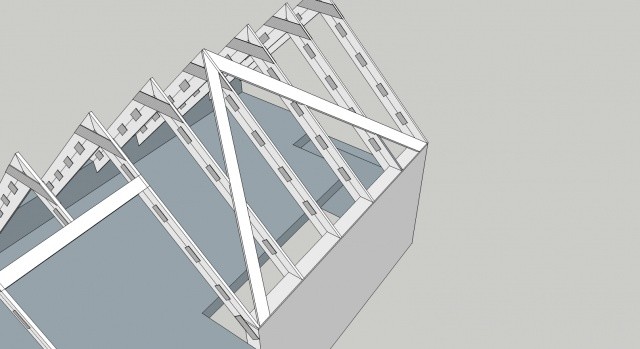
My dream scenario is "V-trusses" where the weight from the roof is absorbed by the side walls. These trusses are prevented from tipping over with the help of roof cladding and an overlaying ridge beam like 45/195. So, no ridge beam is taking up the force and distributing it in the gables. Unfortunately, I must have the same pitch on the outer roof as the inner roof due to space constraints since the house is narrow.
Grateful for all ideas. /Robert
A major difference between the mill house and your drawing is the steel structure that supports the loft floor and makes it possible to have the overhang at the beam level. I suspect that there is also a (hidden) steel structure in the outer wall that holds the outer wall together.
In your drawing, I don't see any supporting details, which makes it very difficult to have a functioning structure.
In your drawing, I don't see any supporting details, which makes it very difficult to have a functioning structure.
Mella: Thanks for your input, yes it's true that the mill house has a steel beam in the outer wall, but how does this help against the deflection of the outer wall? I won't have the overhang of floor joist beams like the mill house, as my supporting beam lies at the outer edge of the loft according to the side view. The question remains, could the roof weight be supported in the outer wall if the dormer's floor joist holds the outer wall against deflection and avoid steel wires as titanium suggested.
At the same time, it's a narrow house with a good roof pitch, the deflection of the outer wall would be stronger if the roof pitch were flatter. Correct me if I'm wrong. The outer wall will be built with 220 studs with cross-bracing on the inside.
Grateful for all solutions.
At the same time, it's a narrow house with a good roof pitch, the deflection of the outer wall would be stronger if the roof pitch were flatter. Correct me if I'm wrong. The outer wall will be built with 220 studs with cross-bracing on the inside.
Grateful for all solutions.
Attached is a link to images from a villa designed by Franson Wreland that also has this solution, but they have probably solved the problem with a load-bearing ridge beam which I want to avoid if possible.
http://www.fransonwreland.com/lidingo.html
http://www.fransonwreland.com/lidingo.html
There shouldn't be any problem carrying the wall with a hidden steel construction inside it. It's just important to attach the standing steel beams to sufficiently large buried concrete piers. I have a timber shed with 8-meter high gables that is "freestanding" and withstands wind loads in this way.
The concrete piers are 3 meters deep and weigh over 5 tons each.
The concrete piers are 3 meters deep and weigh over 5 tons each.
Last edited:
The house will be on piers, but I think a hidden steel construction might still be too advanced for me. It seems like it's leaning more and more towards a load-bearing ridge beam. My problem, however, is not the load-bearing capacity of the outer wall as this will be heavily oversized. I'm mostly worried about the wind load when the floor joists are "divided".
Here is a picture of my intended construction.
Here is a picture of my intended construction.
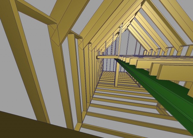
However, I guess that in the original house, as Cem writes, there is a hidden steel structure just like a cage. Doing this solely in wood must be an even bigger challenge ")
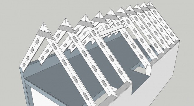
Couldn't let go of your thoughts on the construction, so I also did some drawing
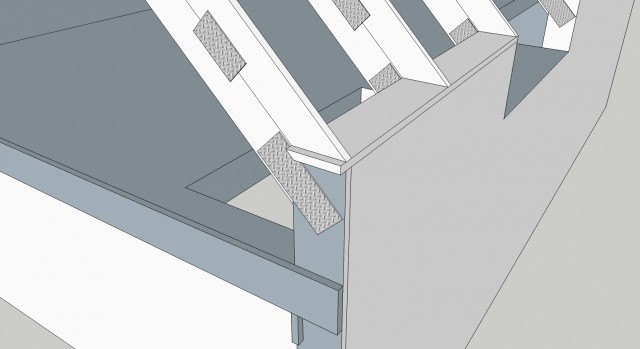
The greatest load is horizontal at the ridge, so you should have substantial reinforcements there.
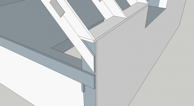
The load in the x-direction at the eaves can be counteracted by adding horizontal hammer beams and connecting the floor structure with the walls. See detail variant 1 and 2. With and without nail plate.
The most critical deformation is in the x-direction on the horizontal hammer beam in the middle of the long opening.
What do you think?
Couldn't let go of your thoughts on the construction, so I also did some drawing
The greatest load is horizontal at the ridge, so you should have substantial reinforcements there.
The load in the x-direction at the eaves can be counteracted by adding horizontal hammer beams and connecting the floor structure with the walls. See detail variant 1 and 2. With and without nail plate.
The most critical deformation is in the x-direction on the horizontal hammer beam in the middle of the long opening.
What do you think?
Exactly, titanium. You understand what I'm aiming for. Thank you for taking the time, it's appreciated. You are absolutely right that you need a strong joint where the hammarband from the gables meets the longitudinal outer wall hammarband. The question then is whether these connection points are sufficient to withstand the greatest force that occurs in the middle of the loft (this span is 6.5 meters), just as you wrote.
Do you think that type of truss would work, and in that way avoid a load-bearing ridge beam? As mentioned, it's a small narrow house of 60 sqm, and my feeling is that this solution is well dimensioned.
Sending some more pictures of your proposal.
Do you think that type of truss would work, and in that way avoid a load-bearing ridge beam? As mentioned, it's a small narrow house of 60 sqm, and my feeling is that this solution is well dimensioned.
Sending some more pictures of your proposal.

Or do you just cast a post in the middle of the wall, that should take all the loads. If you are going to place the house on plinths anyway, it won't be any extra work to cast a larger plinth in the middle with an iron plate on top that is anchored in the post's reinforcement. Then weld an H-beam that stands on the plinth.
Not a bad solution at all. d^_^b If you take your concept and make a "horizontal truss" between the 220s (embedding it), this should be rock solid. I have also decided to have the elevated wall lives in the dormer as well, and if you let the wall plate run around the whole house, it should create a strong junction. I also considered having double wall plates on top of the elevated wall lives, which should further counteract the bowing at the loft opening.
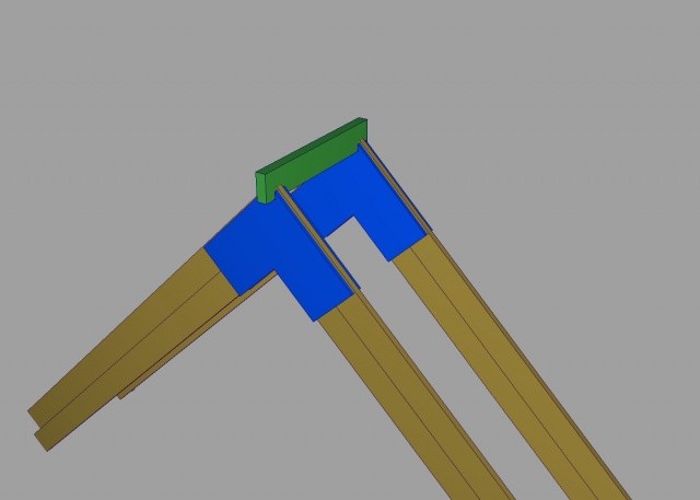
Now I wonder how best to splice the trusses at the ridge, would a nail plate be sufficient? Otherwise, you could glue and screw a plywood sheet on each side. Additionally, it could be considered to recess the superimposed ridge beam slightly into the top. (see picture)
Gratefully accepting more thoughts. / Robert