Hello,
There is a post foundation under the summer house that is on its last legs and I've started sketching out a plan for action.
The cabin needs to be leveled out a bit, and new posts must be installed at the required depth.
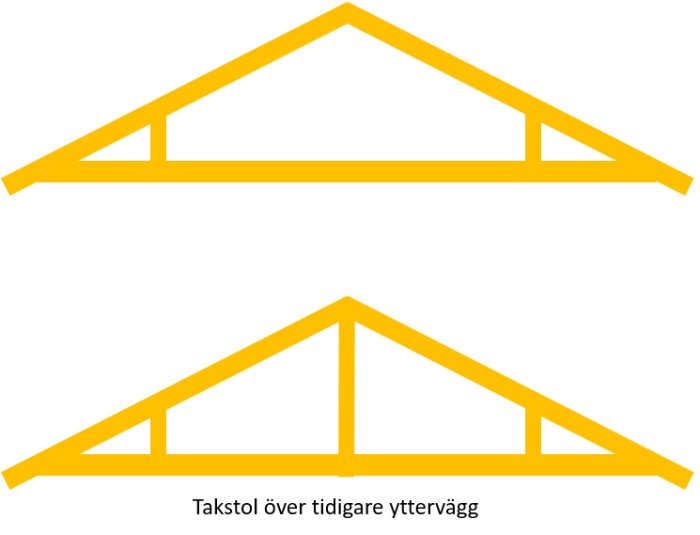
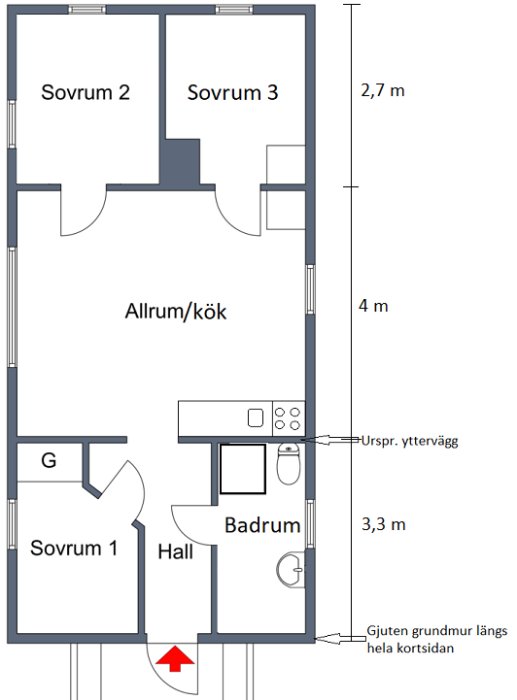
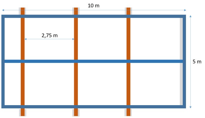
The current foundation is, as mentioned, posts in three rows with about 2.5 meters between them. However, one short side of the cabin rests on a cast wall that extends down to frost-free depth (furthest to the right in the picture).
One idea I have is to use steel beams under the house, lift with jacks, and then let the beams rest on the new posts (only support the beams with posts under the outer edges of the beams), meaning letting the beams remain as part of the foundation.
Does the load need to be calculated differently than for a regular line load since the floor joist only rests on three points (outer walls and support beam in the middle under the house) on the beams?
I spontaneously think that HEB180 would suffice, but as mentioned, I need to calculate it a bit more closely.
With the current geometry, I don't think the difference will be significant between calculating it as a line load or as three point loads. I haven't checked if HEB 180 is sufficient. Go with the line load.
1. I don't quite understand what you mean, are you referring to whether the load on the floor joists needs to be calculated differently (if so, the answer is no, the load on the floor joists is a line load) or are you referring to whether the load on the steel beams can be considered a line load or point loads?
If it's the latter, I don't understand why you don't calculate the loads that come down as point forces. If you're only going to have foundation blocks supporting the outer edges of the beams, you consider the steel beam as freely supported. In that case, there's a 50% difference in the maximum moment whether the load coming down on the beam is 3 point forces or a line load.
2. Is the idea that you're going to lift the house and cast new foundation blocks that are longer than the old ones?
Hello and thank you for your responses,
I was referring to the load over the steel beams and thought I could simplify it for myself by calculating on a line load instead of a point load since I haven't previously calculated on point loads, but I can always learn
The idea with the plinths is that those existing under the exterior walls (not shown in the sketch) are replaced with the ones the beams rest on, and the existing ones in the middle under the cabin (also not shown) will remain, but without contact with the beam, as they move with the frost.
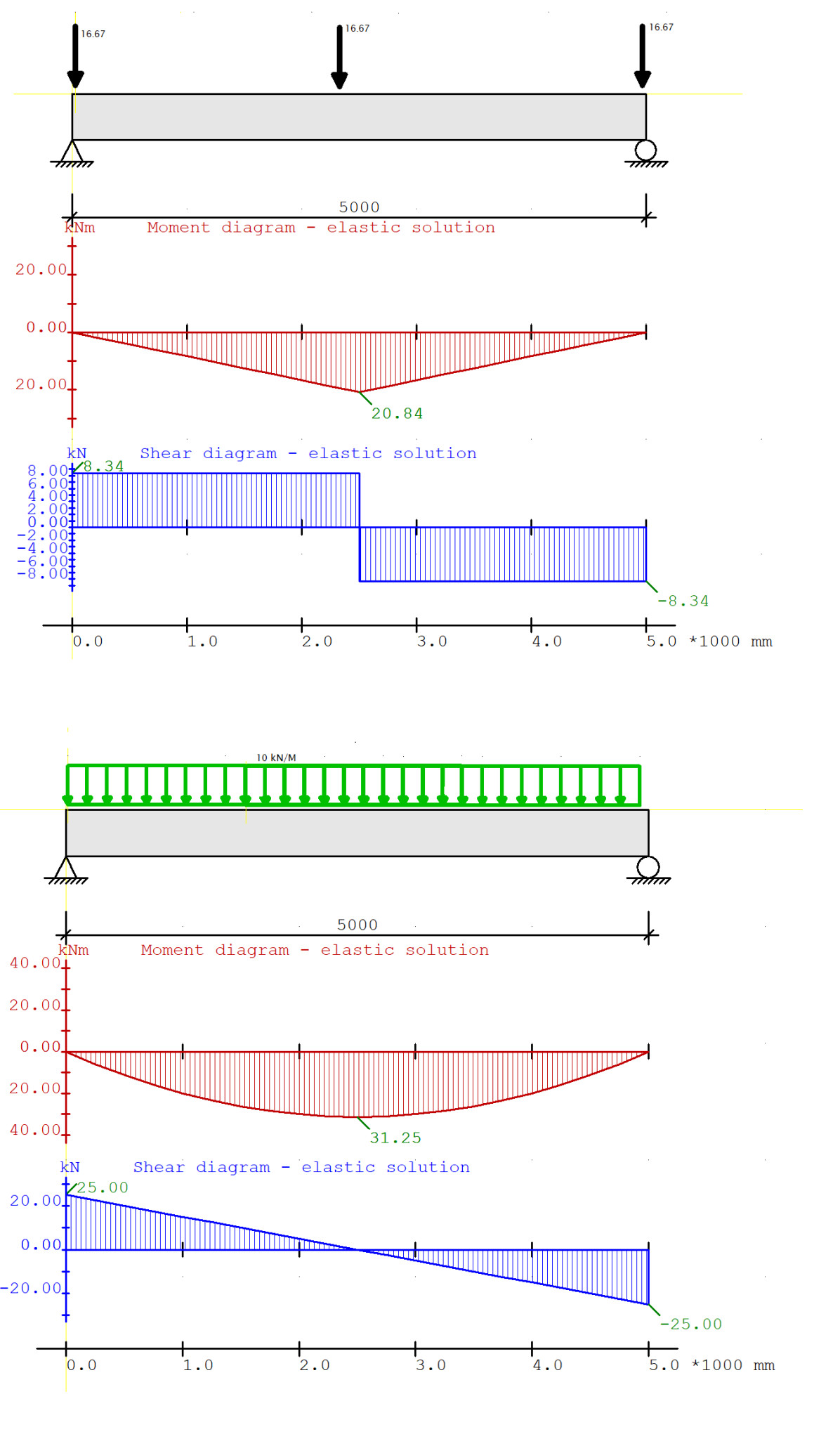
Okay, yes, I would count as point loads anyway as it is most representative. I've attached an image showing the difference between line load and point loads. Let me know if you need help with the dimensioning.
Thank you!
Just realized that I still don't really know how to calculate the line load in this case since the greatest weight (presumably) will be over the exterior walls.
Difficult to estimate the weight of the house, but I wouldn't think more than 7-8 tons (frame 45x95 with insulation, wooden exterior panel and some soft wood fiber board inside and metal sheet roofing). However, planning for potential additional insulation and gypsum cladding inside. No major interior installation, the heaviest (besides potential residents) is the hot water tank of 100 liters. Snow zone 4-4.5 (Tänndalen), that alone gives a roof load of 264 kN (66 sqm x 4 kN/m2).
At first, I thought I could use the same as the bottom chords of the roof trusses that span over the total width of 5 meters and with some "reversed engineering" estimate what they are designed for.
If you have any nudge in the right direction, I would be very grateful
Okay, yes, I would definitely count it as point loads as that is most representative. Attaching an image of the difference between line load and point loads. Let me know if you need help with the sizing.
Should it really be 3 point loads of the same size? The point loads under the outer walls must be much larger as they handle the roof and wall weights? Line load on the beam closest to the gable feels right.
You're right, I just wanted to demonstrate the difference.
KKane said:
Should it really be 3 point loads with the same size? The point loads under the outer walls must be much larger since they handle the roof and wall weights? Line load on the beam closest to the gable feels right.
As you mentioned, I just wanted to demonstrate the difference. Along with the gable, they are still point forces theoretically, but since the studs are so close together, there's no significant difference with a line load.
In the transverse direction, however (which I assumed hordak referred to), that's not the case.
Thank you!
I just realized that I still don't quite know how to calculate the line load in this case since the largest weight will still (probably) end up over the outer walls.
Difficult to estimate the house's weight, but I wouldn't think more than 7-8 tons (stud frame 45x95 with insulation, wooden cladding on the outside, some soft wood fiberboard on the inside, and sheet metal on the roof). However, planning for potential additional insulation and gypsum cladding on the inside. No major internal installation, the heaviest (besides possible residents) is probably the water heater at 100 liters. Snow zone 4-4.5 (Tänndalen), just that gives a roof load of 264 kN (66 sqm x 4 kN/m2).
Initially, I thought I could use the same as the truss's bottom chords spanning the total width of 5 meters and with some "reverse engineering" estimate what they are designed for.
If you have a nudge in the right direction, I am very grateful
You have point loads coming down from the trusses, which then get distributed down into the studs and finally down onto your beams on the long sides (approximate line load by taking the sum of the point loads divided by the length of the wall). In addition to the load from the roof, you have the weight of the outer wall, which you can calculate and divide by the length of the wall to get the line load.
1) The new pedestals that the steel beams rest on are placed outside the outer walls. Therefore, the external point loads are quite close but not directly over the support of the steel beams.
2) The load distribution on the three original bearing beams (which should rest on the steel beams) cannot be known in detail without knowing the house's construction. This especially concerns whether there is a hjärtvägg. If this is the case and the house has normal roof trusses (i.e., not trusses), the middle bearing beam will be subjected to significantly larger loads.
I made it easy for myself by thinking that the digging for the new plinths can be done outside the outer walls, thus minimizing the risk of affecting the existing plinths during new excavation. But upon closer reflection, a temporary extra support and some reasonable excavator operators should be able to dig at an angle under the outer walls so that the new plinths end up directly underneath.
I think the roof trusses can be classified as ordinary, although there are support legs about 1 meter in from each eave. Upper arms according to documentation 2"6, lower arm 2"5 (built in 1955). Floor joists 2"7. There is no load-bearing wall, but there is a former outer wall that, after an extension, serves as an inner wall (under which the first row of the old plinth foundation begins), where the pressure is probably higher over the middle beam, as the roof truss over this wall also has a post from the ridge to the lower arm.
The wall between bedrooms 2 and 3 is a very simple partition wall with 45x45 studs with gaps between the wall and the ceiling. However, I intend to build a new wall there with 45x95, which should also increase the pressure on the middle beam.
1) The new footings that the steel beams rest on are placed outside the exterior walls. The external point loads thus end up quite close but not over the steel beam's supports.
2) You cannot know the load distribution on the three original bearing lines (which will rest on the steel beams) in detail without knowing the house's construction. This especially applies to the question of whether there is a central wall. If so, and the house has standard trusses (i.e., not trusswork), the middle bearing line will be subjected to significantly larger loads.
It doesn't really matter whether the load is considered as point loads or line loads along the long side, if the point loads are near the supports.
I agree with point 2, but as I said, it was just to show the difference between line load and point loads that I interpreted he meant in the transverse direction.
Just to keep up and respond as accurately as possible, is "tvärriktningen" perpendicular to the long side, i.e., the same direction as the roof trusses?
Just to keep up and respond as accurately as possible, the cross direction - is it perpendicular to the long side, i.e., the same direction as the roof trusses?
Correct
Vi vill skicka notiser för ämnen du bevakar och händelser som berör dig.

")
hordak said:
Thank you!