To learn more about deflection and strength calculations, I thought I'd ask for help with a calculation example.
Conditions:
Carport L8000xB6000 mm
Height from concrete slab to roof truss 2500 mm
Glulam column 115x115 mm
4 pcs 45x120 glued-laminated C24 rafters at point B
Glulam beam 115x315x6000 mm
Heavy outer roof (concrete tiles, plywood)
The roof extends 300 mm beyond the roof trusses
Light inner ceiling (plywood)
Freestanding W roof trusses, 6000 mm wide, 27-degree pitch
EDIT: I'm including these values to have something to calculate from:
Snow load: 2,5 kN/m2
Self-weight of outer roof: 0,9 kN/m2
Self-weight of inner ceiling: 0,25 kN/m2
This gives a roof load of 3,65 kN/m2
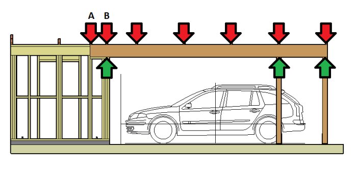
The roof trusses are spaced at 1200 mm, but due to the carport being 8000 mm long, the spacing will be shorter between two of them. The beam is inserted into the storage area about 400 mm. My question now is where the leftmost roof truss on the beam should be located, at point A or point B:
How much is the deflection on the beam reduced if I choose point A? And how do I calculate the deflection?
Only the three truss loads that land on the glulam beam's largest span affect the deflection. The other trusses land over a column (regardless of whether you choose A or B) and therefore do not cause bending in the beam. The formula for calculating the deflection of a simply supported beam is 5qL^4/384EI. q = distributed load, L = span, E = modulus of elasticity, and I = moment of inertia. It is important to use the correct units for the different factors to obtain a comprehensible result.
Okay, let's start by calculating the deflection for the large opening which is set at 4300 mm.
q, distributed load: 3.65 kN/m2 we have. The total width of the trusses is 7 meters which gives a load per meter of 7x3.65=25.55 kN/m. The support length is 4.3 meters which gives 4.3x25.55=109.865 ~110 kN for the entire roof. We divide this by two since there are two sides. 110/2=55 kN.
L, span I assume is 4300 mm (what unit should it be?)
E, modulus of elasticity is trickier for a novice, but I found a table from Moeven (Glulam Handbook) where I found that a GL30c beam has a characteristic modulus of elasticity of 10800 N/mm2. There was also parallel/perpendicular to the fibers, is it characteristic we should use?
I, moment of inertia I can't find! I saw a formula in a thread here on the forum, but couldn't decipher what the numbers in it were.
q is a distributed load that should act per meter, so 55/4.3= 12.8kN/m
Edit: it should really be calculated as point loads for each truss and not a common load
Ok! I understand that it obviously affects where on the beam the loads occur. And then, of course, the follow-up question is how do I incorporate that into the formula?
While we're on the topic of loads, should I add anything for wind load? Like when the roof acts as a sail and the wind pushes the roof down towards the ground?
The moment of inertia of the beam is calculated using the formula b*h^3/12. A 115x315 beam thus has a moment of inertia of 29954 cm4. Snow load is always calculated in the horizontal plane. A 6 m wide truss on c/c 1200 mm is then subjected to a snow load of 6*1.2*2.5 = 18 kN, of which 9 kN is supported by one bearing. I disregard potential shape factors. The roof's self-weight on a truss becomes 8*1.2*1.15 = 11.04 kN, i.e., 5.52 kN per bearing. Each truss thus represents a point load of 9 + 5.52 = 14.52 kN. 14.52/1.2 m = 12.1/m. When these values are inserted into the formula 5qL^4/384EI with the correct units, the result is 16.7 mm.
The moment of inertia of the beam is calculated using the formula b*h^3/12. Therefore, a 115x315 beam has a moment of inertia of 29954 cm4. Snow load is always calculated in the horizontal plane. A 6 m wide truss with c/c 1200 mm is subjected to a snow load of 6*1.2*2.5 = 18 kN, of which 9 kN applies to a single support. I disregard any shape factors. The self-weight of the roof on one truss is 8*1.2'1.15 = 11.04 kN, i.e., 5.52 kN per support. Each truss thereby represents a point load of 9 + 5.52 = 14.52 kN. 14.52/1.2 m = 12.1/m. If you input these values into the formula 5qL^4/384EI with the correct units, the result is 16.7 mm.
Thanks, Justus! I repeat for my own sake (and for others who may be reading):
I=b*(h^3)/12
b=11.5 cm
h=31.5 cm
I=11.5*(31.5^3)/12
I=29953.546875 cm4 I=29954 cm4
Attaching an image of the truss in question:
Surely the roof width should be 7 meters when we calculate the snow load?
I.e., 7*2.5=17.5 kN/m which gives 17.5*1.2/2=10.5 kN point load per support?
And then there's another question about the roof's own weight per meter; should it in this case be calculated (3.9+3.9)*0.9+(3.9+3.9)*0.25=7.02+1.95=8.97 kN/m for the entire roof? Meaning that you take into account the angle of the truss and use the total length of the top chord?
Point load self-weight roof per support becomes 8.97*1.2/2=5.382 kN
Point load on each support becomes 10.5+5.382=15.882 kN
If q distributed load should be in kN/m, we calculate back again: 15.882/1.2=13.235 kN/m
Can I get help with the correct units for 5qL^4/384EI?
Surely the roof's width should be 7 meters when calculating the snow load?
Absolutely, although it wasn't clear from previous explanations. For the roof's own weight, you obviously calculate the entire roof area. If you use the units N/m, m, N/m2, and m4, you will get a result in meters. Quite a few decimal places, indeed. You can use any units you want as long as you do it consistently. A tip: The calculation is much easier to troubleshoot if you input it into an Excel sheet. Additionally, you can change the parameters to test the consequences.
Vilket ger mig en nedböjning på 0,0182 meter, dvs 18,2 mm.
Detta ger L/236 vilket väl inte är önskvärt? Jag har bett Martinsons Byggsystem räkna på balken och jag fick deras beräkningsresultat på mail. Där får dom följande deformationer:
Abs. - total last: -13 mm
Abs. variabel last: -9 mm
Dom har troligen inte samma ingångsvärden som jag tagit här ovan, så nu vill jag kika på takets egenvikt.
Kanske är 0,9 kN/m2 för högt räknat för mitt yttertak? Vi går igenom det:
Betongpannor: Benders Palema
Ströläkt/bärläkt: 25x36 gran, ströläkt på cc600mm, bärläkt på cc356mm
Takpapp: Mataki MB320 vikt 2 kg/m2
Råspont: 20x120 gran
Jag får leta efter vikt/m2 på respektive post, men om någon har det i huvudet så fyll gärna på.
Total weight: 57.5+7.052+0.8=65.352 kg/truss or 0.640884 kN/truss
*Phew...
I previously wrote that the self-weight for the roofing itself was 52.5 kg/m2, which more precisely is 0.514849 kN/m2. If we now try to combine all this into kN/m for our/my beam, we'll get:
Roof 0.514849*7.8/2=4.0158/2=2.0079~ 2 kN/m
Trusses 0.640884/1.2=0.53407~ 0.53 kN/m
Snow load 10.5/1.2= 8.75 kN/m
(I am omitting the ceiling at this stage!)
2+0.53+8.75= 11.28 kN/m
Plug that into the formula, and I get 15.5 mm deflection or L/277 :/
This gives (thanks to my great Excel tool, thanks for the tip!) a deflection of 15.09 mm and L/284.86
Are E= 10800000000 N/m2 and I= 0.00029954 m4 correct, or is there something there that needs to be checked?
Reducing the free span makes the deflection quickly become smaller as well. If I reduce the span to 4 meters, the deflection becomes 11.3 mm and L/353.88.
The origin of the thread was to determine where the truss on the far left of the beam should be placed to minimize deflection the most. There will be a moment around columns 1 and 2 in the image below which will counteract the deflection.
The question is how much it affects... The result 15.09 mm is based on a simply supported beam without aiding moments.
I= 0.00029954 cannot be changed unless the beam's dimensions are altered. The modulus of elasticity has slightly different values depending on the context. For deformation calculations, GL 30c typically has an E-modulus of 13000 MPa. However, it's not incorrect to calculate a bit lower. If you had a distributed load between pillars 2 and 3, it would have caused a negative moment over pillar 2, which would have counteracted the deflection. As it is, you don't have that because the trusses land directly over the pillars.


")

murak said:

