2,231 views ·
14 replies
2k views
14 replies
Mockfjärd Elementhus AB, Load-bearing
I, just like many others, managed to buy a house made by Mockfjärd Elementhus AB. Without knowing it at the time of purchase, I am currently in the process of completely renovating the house. I've come up with some clever solutions for installing flexible conduit for the electricity.
And I've obtained some drawings, although I don't understand them at all. I have zero experience reading blueprints, but I've managed to figure out the elements' distribution at least.
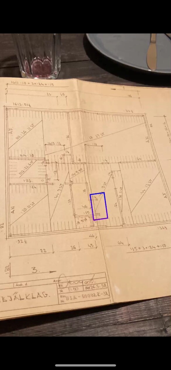
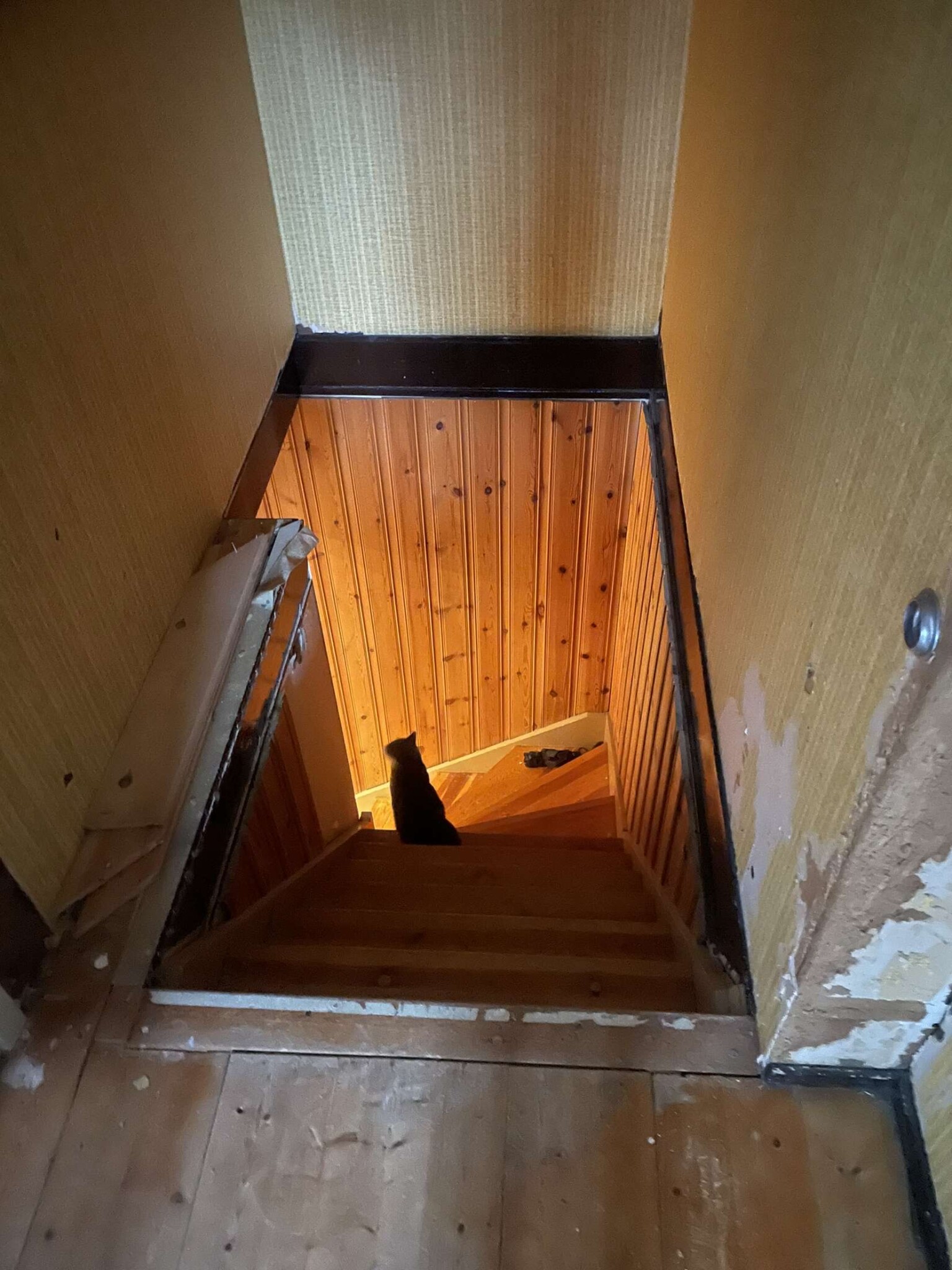
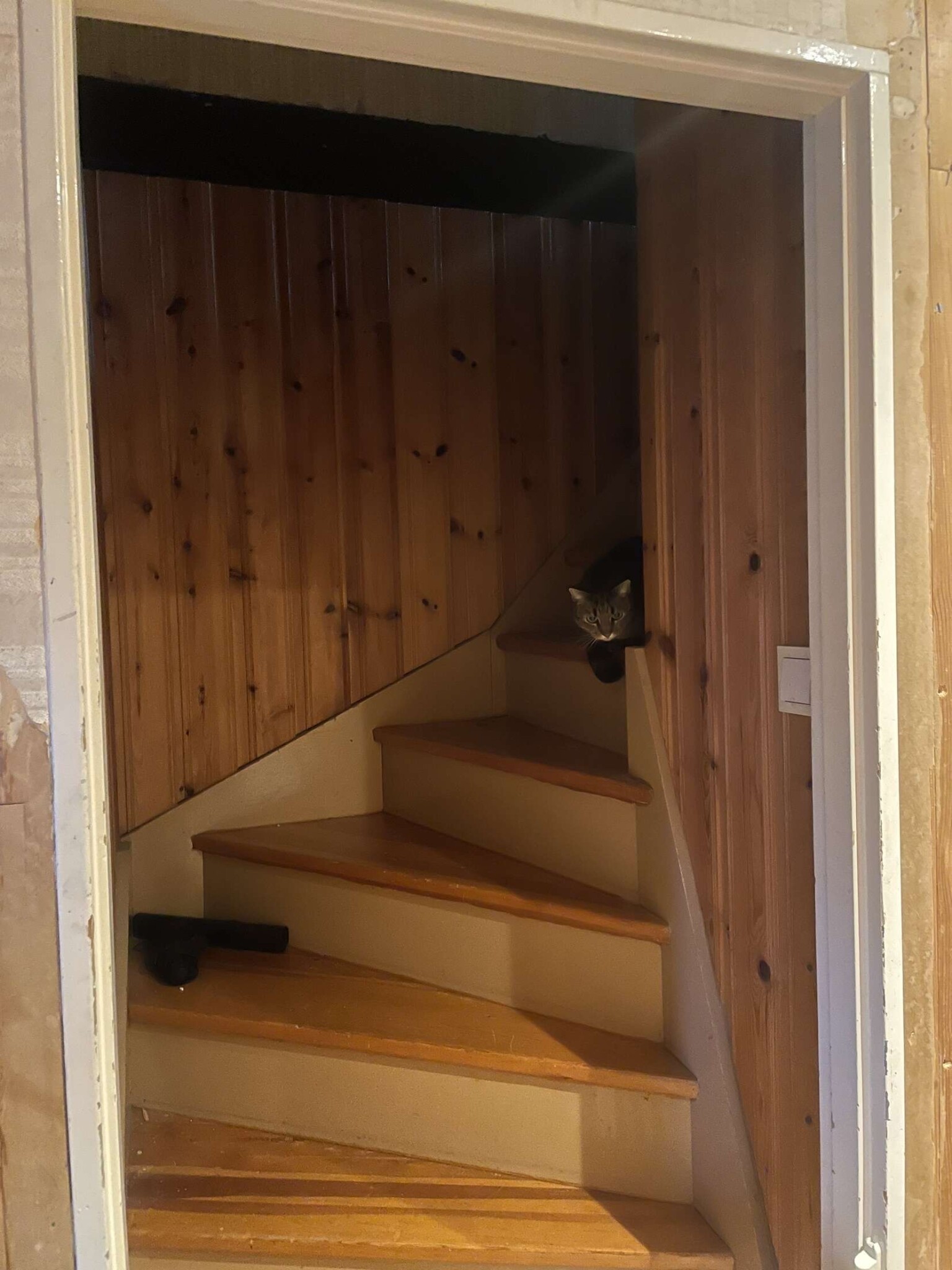
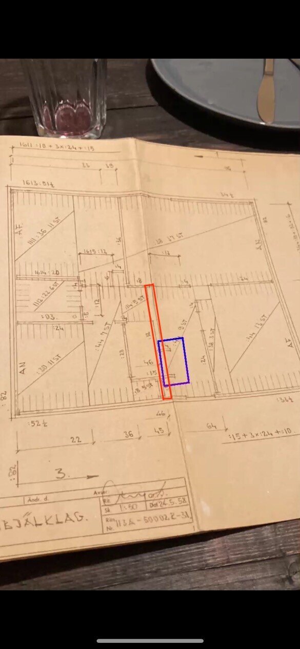
Back to the point, I would like to remove the part marked in the picture, which is the staircase up to the upper floor (entrance). Can I do it? Please explain thoroughly! And preferably no guessing if you're not familiar with these houses.
If drawings of the upper floor are needed, I will try to provide one.
Thank you very much in advance /Mathias
And I've obtained some drawings, although I don't understand them at all. I have zero experience reading blueprints, but I've managed to figure out the elements' distribution at least.
Back to the point, I would like to remove the part marked in the picture, which is the staircase up to the upper floor (entrance). Can I do it? Please explain thoroughly! And preferably no guessing if you're not familiar with these houses.
If drawings of the upper floor are needed, I will try to provide one.
Thank you very much in advance /Mathias
Anyone?M Mathias94 said:I, just like many others, managed to buy a house made by mockfjärd elementhus AB. Without knowing it at the time of purchase, and am currently in the process of completely renovating the house. I've come up with some clever solutions for running flex conduits for the electricity,
And I've got some drawings, but I don't understand them at all. Since I have zero experience in reading drawings, but I've managed to figure out the elements are distributed at least.
Back to the point, I would like to tear down the part marked in the picture, which is the staircase to the upper floor (in the entrance) should I dare to do it? Please explain thoroughly! And preferably no guesses if you aren't familiar with these houses.
If drawings are needed for the upper floor, I will try to obtain a drawing of that as well.
Big thanks in advance /Mathias
Have been living in an Elementhus for a number of years, so I am fairly familiar with the construction. Am I understanding you correctly that it is like a "portal" over the stairs to the upper floor, and that it is the one you are considering removing?
I've come up with some clever solutions for routing flex conduit for the electricity
Nice to know I'm not alone in having bought a Mockfjärds house without realizing it before the purchase...
Sorry to hijack the thread. But I think many are interested. Maybe you can describe in a new thread:
Clever solutions for routing flex conduit sounds very interesting. Can you describe how you did it?
Last edited:
I can take some photographs when I get home from work and write about how I proceeded. 👍O Ombyggnationsnewby said:
Here are the pictures of the stairs, better late than never. It's been a bit busy, so it slipped my mind.B bearmaniac said:
I'll try to take a picture of how we solved the electricity tonight as promised to you all!
") but I can't promise I'll remember. But it will come, I promise.
but I can't promise I'll remember. But it will come, I promise.Yes, we do have a basement, by the way.
Oh, but you have the floor beams exposed on the upper floor. Perfect! Then you can see which walls absolutely cannot be taken down, and which walls only provide support.
I'm having a hard time understanding how the red-marked element (or is it several?) looks. Does it have any joints? Does it look different from the other elements in any way? I simply don't quite understand why it isn't included in the section that's drawn directly to the right of it (on the blueprint, that is).
I'm having a hard time understanding how the red-marked element (or is it several?) looks. Does it have any joints? Does it look different from the other elements in any way? I simply don't quite understand why it isn't included in the section that's drawn directly to the right of it (on the blueprint, that is).
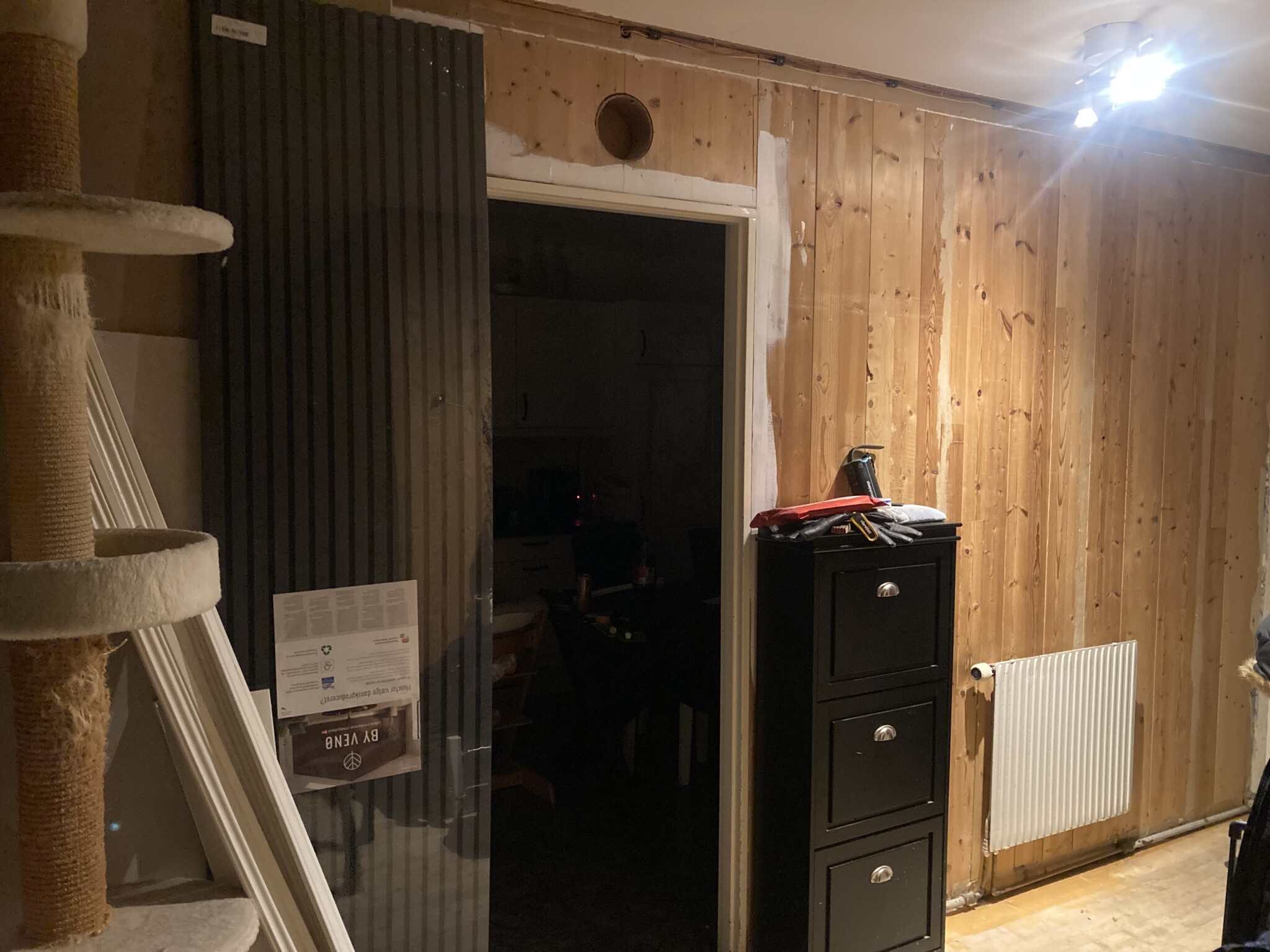
The blue is just an extension of the elements where there is currently a door frame. So my spontaneous guess is that they just built it out so there would be a door to the upper floor/attic. I can take a few more photos if that would help? Or a video.B bearmaniac said:Oh, but you have the floor elements exposed on the upper floor. Perfect! Then you can see which walls absolutely cannot be removed, and which walls simply provide support.
I'm having a bit of difficulty understanding how the red-marked element (or is it several?) looks. Does it have any seams on it? Does it look different from the other elements in any way? I simply don't quite understand why it hasn't been counted in the section drawn directly to the right of it (on the drawing, that is).
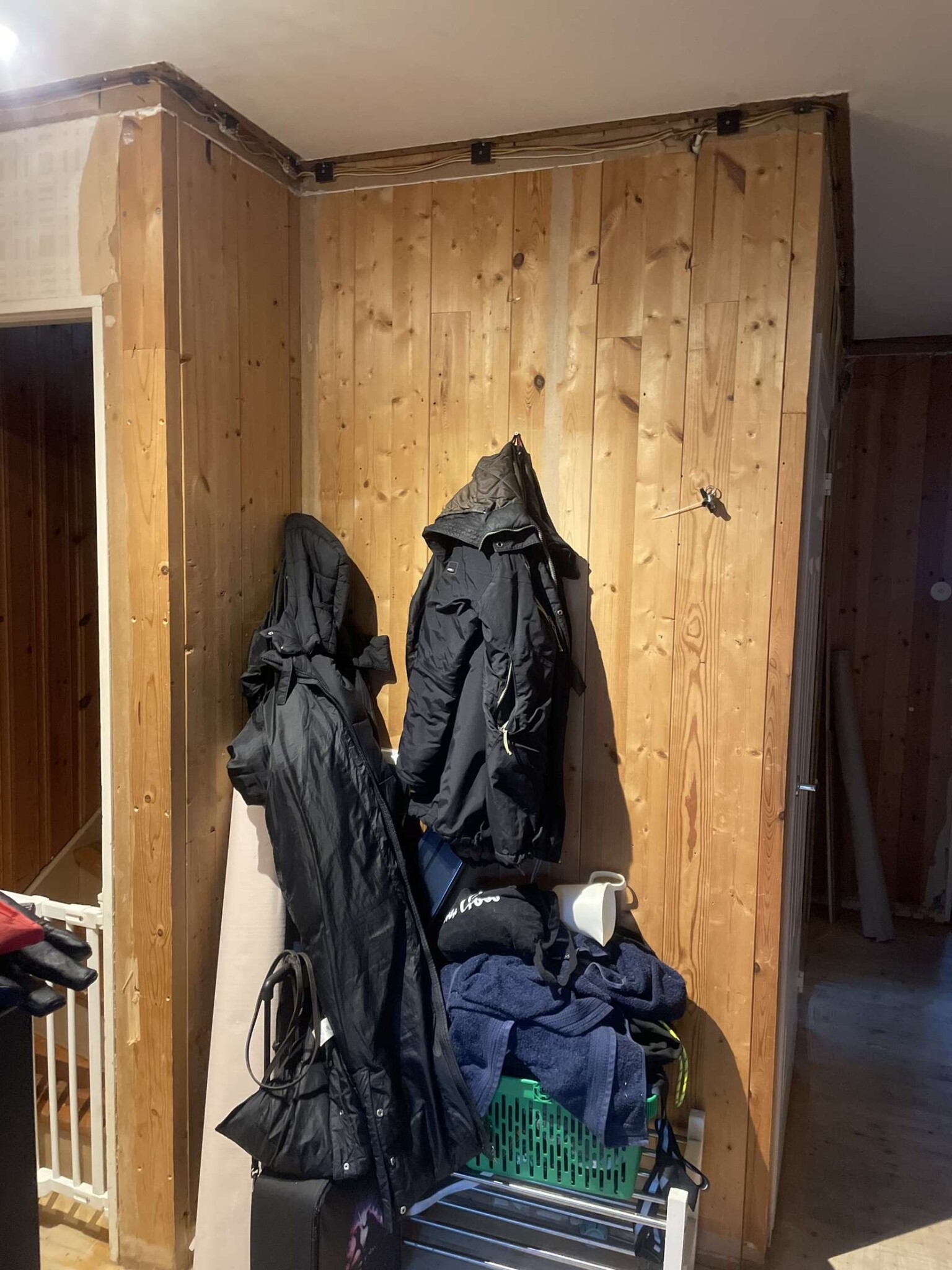
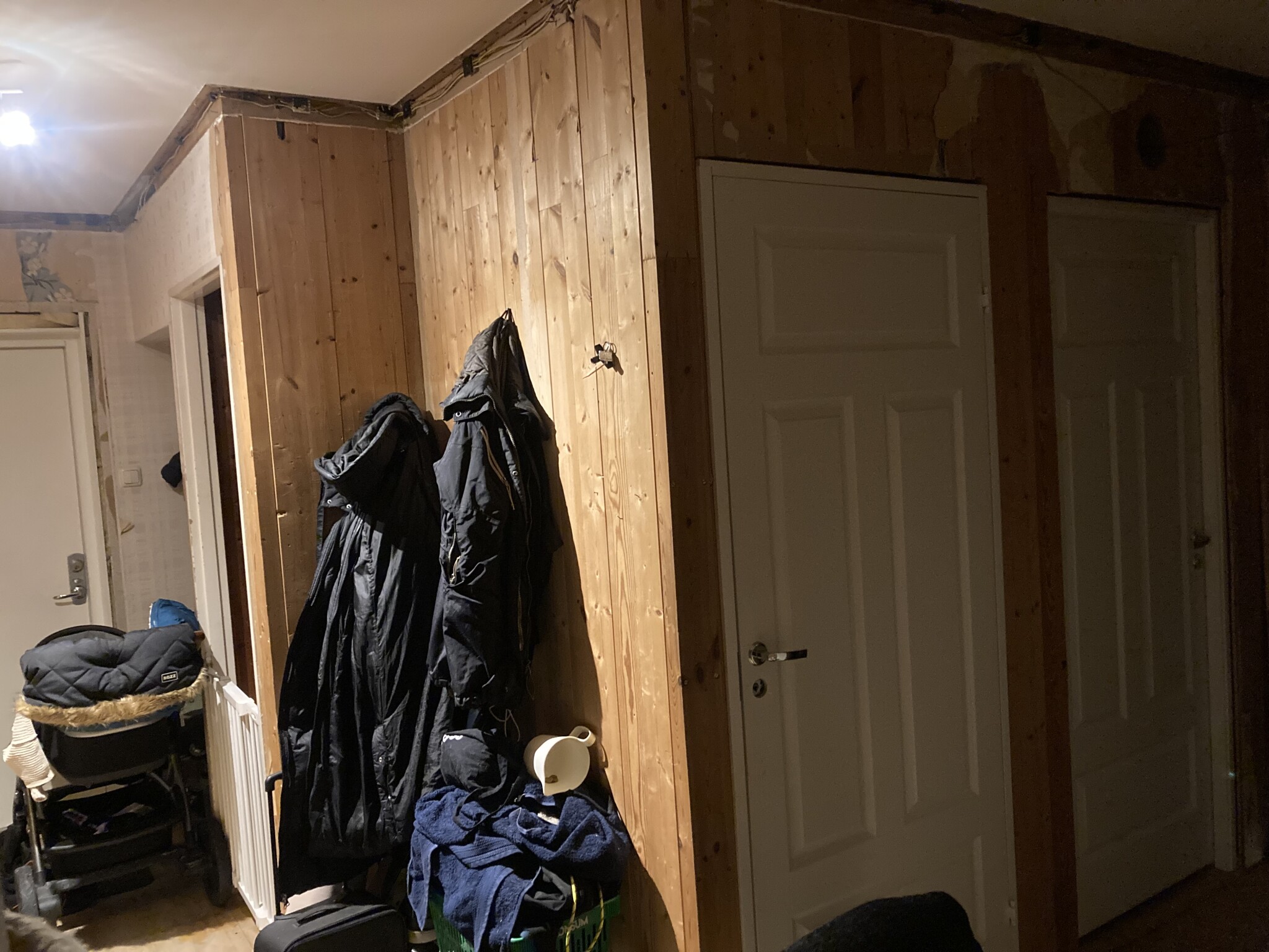
You see in the picture where there are lots of jackets hanging and a shoe rack. The short wall there with a frame in it. Is the blue marked in the pictureB bearmaniac said:Oh, but you have the floor elements exposed upstairs. Perfect! Then you can see which walls absolutely cannot be taken down, and which walls just provide reinforcement.
I'm having a bit of trouble understanding how the red-marked element (or is it multiple?) looks. Does it have any joints on it? Does it look different from the other elements in some way? I simply don't quite understand why it's not included in the section drawn directly to the right of it (on the drawing, that is).
I have tested two variants of electrical wiring.O Ombyggnationsnewby said:Have come up with some clever solutions for running flexible conduit for the electricity
Nice to know I'm not the only one who bought a Mockfjärds house without realizing it before the purchase...
Sorry to hijack the thread. But I think many are interested. Maybe you can describe in a new thread:
Clever solutions for running flexible conduit sounds very interesting. Can you describe how you did it?
In the first two rooms, I ran flexible conduit hidden behind the original hollow cornice. A bit tricky as I also chose to embed 1-2 junction boxes in each room, placed high up on the wall.
Unfortunately, the original solution doesn’t have accessible junction areas.
The solution in these two rooms wasn’t super great because in several places the radii of the flexible conduits were somewhat tight. This can be a problem if you later want to replace or add more conductors.
In the remaining rooms, I chose to lower the ceiling with 45mm battens and new plasterboard. This way, I could run new wiring in this space and place ceiling boxes where all connections are made, which are then concealed under ceiling lights. This of course involves more work and you lose a bit of ceiling height. But it becomes much easier to run wiring straight and without complicated bends.
Yes, exactly. But I'm wondering about how the element ("the box") that is on the drawing closest to the right of the stairs looks (the element I have marked in red). Is it about half the house long? Or is the element divided into sections? The element marked in red is drawn differently than the long elements laid further right of it, and I'm not sure why.M Mathias94 said:
The element to the right runs through half the house more or less exactly. And the chimney is in the drawn square on the drawing.B bearmaniac said:Yes, exactly. But I'm wondering about the element ("the box") that in the drawing is nearest to the right of the stairs (the element I have marked in red). Is it approximately half the length of the house? Or is that element divided into sections? The element marked in red is drawn differently from the longer elements that lie just further to the right of it, and I'm unsure why.
The element where I'm removing the wall goes from the front door (the beginning of the element downwards as seen) and then there is a hallway that is shaped and leads to the left in the image, the stairs to the basement go just under the stairs up.
Attaching pictures of the element against the kitchen and the element against the stairs
Hope you understand what I mean 😁
Then I interpret it as what I have circled in red, believing it was a single element, is actually two elements?
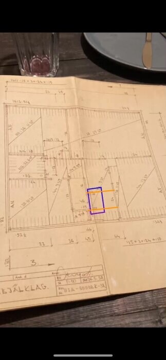
If so, I would be careful about taking down the protruding wall - I wouldn't do it without further reinforcing measures. My feeling, after living in a house like this for eight years, is that it's enough to place a solid cross beam (45x170+) in the ceiling, as a replacement for the small wall stubs that are removed (in orange on the drawing). These beams should ideally be attached right through the entire floor joist with 8x240 screws, at least one screw per element. If it is also possible to attach them to the respective wall on the left in the drawing, the construction will become even more stable. The impact on the house should be minimal with this measure.
It should be emphasized that this is an educated guess, not a structural engineer's statement. I base my feeling, among other things, on the fact that in my house someone had removed a load-bearing wall about 8 elements wide in one spot, and the floor joist didn't collapse for several years (how many is unclear, but at least four years, probably much more).
Click here to reply