Compression perpendicular to the fibers 2.5 Mpa for C24 timber.
This unit can be converted to a (more understandable for me) Nm/cm^2 => 250 N/cm^2
This value doesn't say anything about whether it's a 45x45 beam or a 170x45 beam... so how should one interpret this number?
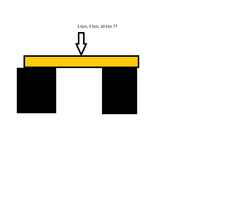
Let's take a simple example that should be manageable to figure out... say we have a beam resting on two solid surfaces 1 meter apart. Now assume we load the beam in the middle over an area that is 4.5x4.5cm, how much can the beam take before it breaks in the middle if, for example, it is a 170 beam with C24 timber? As I said, I want to get a sense of the order of magnitude...
In your example, you are probably not primarily interested in the permissible pressure load but in the value for bending parallel to the fibers at 24 MPa. Based on the geometry of your board, you need to calculate the bending stress that occurs due to your load. The size of the bending stress depends on the length between the beam's supports and the beam's cross-sectional geometry (bending resistance). Your load should be designed so that it does not cause a stress greater than the allowable bending stress (24 MPa).
I calculated it on my calculator.
With a beam 1m apart between supports. Point load in the middle of the beam. C24 lumber. This gives me:
For a 45 beam: about 150 kg.
For a 170 beam: about 2000 kg.
I haven't double-checked though, so there's a chance it might not be correct.
And then it may be necessary to look at shear strength and buckling in certain cases as well. However, the above is normally sufficient to calculate the strength for, e.g., floor joists that are braced at the top edge by an overlay and are not weakened by holes.
However, floor structures are sensitive to sway and deflection, so larger dimensions are often required for these joists than what pure strength demands.
Stress = 6*M/(b*h*h) (maximum allowed 24MPa according to previous post)
Moment = F/2*l/2 = F*l/4
F = 2*S*b*h*h/3*l
Beam 45x170 b=45 h=170
Distance between supports l=1000
F = S*30*170*170/1000 = 24*30*170*170/1000 = 20.8 kN i.e., approximately 2 tons
But this is really unimportant as deflection sets the limit much lower as mentioned earlier.
The background to my questions is that I want to calculate what dimension I need for studs to support a wall where, for example, there is 1 meter between supports. I was thinking of setting 2 double 170 studs through a wall, i.e., a total of 4 170 studs lifting up the wall from the top of the window (which I have removed, hence I want to lift there). I have no idea if this is too risky or extremely oversized myself... I want to be on the safe side so exact figures are not interesting, but rather if the idea can be dismissed or not. If now a stud could support 2 tons, this construction would thus handle roughly 8 tons IF all are loaded equally... not extremely oversized in other words.....
What size I-beam corresponds to a 170 stud, do you think?
Better to calculate the deflection in this case, I would think. That is, how many mm you can accept the beam to bend down.
If you surf a bit, you can probably find the formulas for this. I can't write anything sensible about it now, have to manage some work at the job too =)
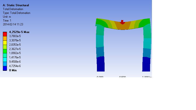
Okay, made a model of a 45x170 beam resting on two supports BUT the material is currently steel.....
I've placed a load of 1 ton in the middle (perhaps a bit off-center) and figuring out how much it bends.
I'm not a mechanics expert, so I'm not really sure what values to change to get the properties of a wooden beam.... Does anyone happen to know what it's called, preferably in English Different in different directions.
The result in this case was a deflection of 0.042mm
Vi kan väl i detta fall säga att du har en fritt upplagd balk med en punktlast på mitten mellan upplagen. Belastningsfallet avgör hur vi går vidare med vår beräkning.
Nedböjningen blir då f=(F*L^3)/(48*E*I)
E=11000 MPa är enligt tabell för C24 virke -> 1,1e10 Pa
I=(b*h^3)/12 (Gäller för balk med rektangulärt tvärsnitt)
Om vi säger 170 regel med en last på 1 ton med 1 meter mellan upplag så får vi:
I=(0,045 * 0,170^3) / 12 = 1,84e-5
f=(9820 * 1^3) / (48 * 1,1e10 * 1,84e-5)=1,01e-3 [m] d.v.s. ca: 1 mm nedböjning.
Men använd inte mitt exempel som underlag för din dimensionering. Jag kan ha räknat eller tänkt fel. Anlita en konstruktör!
hmmm your E=1-1e10Pa what is that constant called?
I can input something called Young's Modulus in the program that directly affects the result. For steel, this constant has the value (2e11Pa).
If I input 1.1e10 instead, I get a deflection of 0.5mm with 1 ton load on a 4.5x4.5cm area in the middle of the beam, maybe it's accurate because you have a point load. It feels a bit strange though that it's double for you... since 4.5x4.5cm should almost be approximated as a point.
In your example, it looks like you have a fixed beam; or rather that the supports and beam are a homogeneous piece. In my calculation example, I have a simply supported beam. That can probably explain why we get different deflection values.
2e11 is the E-modulus for steel... I have always calculated with 2.1e11, but it is accurate enough anyway. My E-modulus of 1.1e10 comes from the table on the wood guide you linked to at the beginning of the thread.
Vi vill skicka notiser för ämnen du bevakar och händelser som berör dig.

")