9,128 views ·
15 replies
9k views
15 replies
multiple k24 = glulam beam?
I'm going to build a one-story holiday home with a shed roof in snow zone 3.5-4 with my brothers.
When looking at the Traguiden dimensioning example for beam/support beams, for zone 4, it results in approximately 1.6 m between the pillars if using 2 pieces of 45x220 C24 and 3.6 m between the pillars if using 90x405 L40 glulam.
I have quite a bit of space on the pillars (large) and would therefore like to have as much distance as possible between them. If you used, for example, 4 pieces of 45x220 C24 properly nailed together with staggered joints, how much could the distance between the pillars be increased without causing too much deflection? Or does it not matter that much since it's the "height" of the beam that provides the most? Does anyone have an idea?
That's the height!
Parallel beams provide less increase in load-bearing capacity than higher ones.
It does NOT work to nail together 45x225 to 45x550! It's the nailing that doesn't work.
Buy laminated wood!!
Parallel beams provide less increase in load-bearing capacity than higher ones.
It does NOT work to nail together 45x225 to 45x550! It's the nailing that doesn't work.
Buy laminated wood!!
Well, I wasn't planning on putting them together "above below," like this:
I
I but rather all four in a row, like this; IIII
(if you understand my "picture" ;-)
So it would create a "beam" with the dimensions 180x220 (4x45=180)
Of course, it won't be as strong as a laminated beam, but at home on the farm, we have 2-story log outbuildings with tile roofs that stand on pillars with 300x300 as the main beam? (Was the timber really that much better back then? ;-)
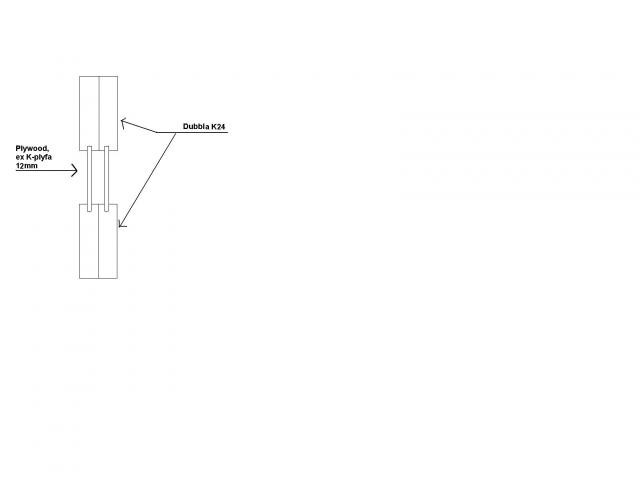
Will become stronger if you just nail together 2 & 2, then groove/mill 12mm wide grooves along the K24 beams and glue cut-out pieces of, for example, K-plypa 12mm into the grooves.
This probably corresponds to at least the laminated beam you mention, and it's quite quick to groove out for the plywood, and 1 sheet goes a long way.
That's the technique "Swelite" and many others use. Call a designer and ask (he'll figure it out in 1 minute), it might even be sufficient with slightly denser simple K24 in this solution.
http://www.environdec.com/reg/stepwise/stepepd0009se.pdf
Best regards, Jawen
Last edited:
Nice Jawen! Thanks!
However, I'm wondering if the "plyfa" beams can serve as load-bearing beams? I mean not in terms of load capacity, as they are probably adequate, but more because in my case they will be under a house as load-bearing beams in an open post foundation. (Granted they are clad, but still... I feel more comfortable with solid wood or glulam). For the roof, however, I am considering this type of beam.
Back to my original thought. The house will be 7x10m. Glulam is a bit expensive for the budget. 4 pcs K24 is easy to work with and quickly done. Is it really that bad? I think that the increased number should reduce each plank's "share of the load" by a quarter... :-S
But I guess I'm thinking wrong...
If you screw together 4 beams side by side (not staggered), the capacity increases 4 times compared to 1 beam for loads in the PLAN OF THE BEAMS. What you need to keep in mind is to use enough screws so that the loads can be evenly distributed between these elements. However, if you have forces perpendicular to the beam's plane and forces in the beam's direction, you need to be cautious with this solution. For a simple carrier line, it should be okay though.
I'm not so sure if a DIY enthusiast can assemble equivalent beams like Swelite. At least when it comes to glulam beams, there are quite specific adhesives and conditions required to achieve full strength and durability. However, I am not familiar with Swelite, so I might be wrong in this case.
By the way, I recall that the wood guide assumes a very low roof pitch; if you increase this, the snow load decreases significantly.
Kalubah, what do you mean by the beams' plane and perpendicular to the beam? Is it the wall above?
In my case, it would be the support beams - the floor joists on top at a 90-degree angle - sill to the wall at a 90-degree angle to the floor joists (i.e., "on top of and following" the support beam)
Does anyone have a formula for how you could calculate the strength and deflection you would get on my type of beam? I've searched but only find it for composite T-type beams...
Thanks for the help so far
I thought I understood what you meant, but after your last post, I'm not so sure anymore... :S Feel free to send a picture.
Anyway, regarding formulas, you know how big the beam should be according to the wood guide. If you follow the below, you're on the safe side:
b1*h1^2 < b2*h2^2
b1=Original beam's cross-sectional width
h1=Original beam's cross-sectional height
b2="Your" composite beam's cross-sectional width
h2="Your" composite beam's cross-sectional height
^2=squared...
This naturally assumes that you have at least as good wood quality as in the wood guide. Theoretically, you should be able to make your composite beam as strong as if it were solid, but it requires you to nail/screw properly. Depending on how you plan to assemble the studs, it might require an enormous amount of nails...
OK
But if I go back to my original idea then.
And settle for 2 "nailed together" 45x220
How could one find out what they can support?
Since the sill on top is a 45x220, it's equally positioned on both "Nailed together 45x220" (NOTE I mean 2 45x220 nailed together and right beside it there is another nailed together 2 45x220. So two parallel beams next to each other but not all 4 45x200 nailed together) I hope someone understands :-D
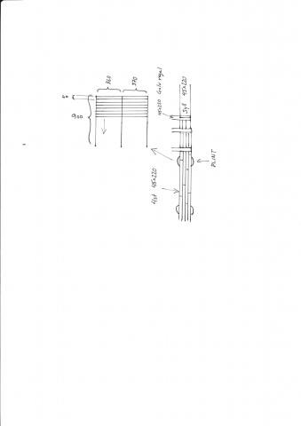
Unfortunately, I'm so bad at CAD so I attach a hand drawing of how I thought. At the bottom, you can see the piers and the 4 45x220 from above.
How strong would such a construction be?
Thanks for the help so far. Regards
But if I go back to my original idea then.
And settle for 2 "nailed together" 45x220
How could one find out what they can support?
Since the sill on top is a 45x220, it's equally positioned on both "Nailed together 45x220" (NOTE I mean 2 45x220 nailed together and right beside it there is another nailed together 2 45x220. So two parallel beams next to each other but not all 4 45x200 nailed together) I hope someone understands :-D
Unfortunately, I'm so bad at CAD so I attach a hand drawing of how I thought. At the bottom, you can see the piers and the 4 45x220 from above.
How strong would such a construction be?
Thanks for the help so far. Regards
and then I forgot the attachment
the image is of support beams and floor joists from above with a detailed view of a support beam on round pillars from above.
as I said. hope someone understands what I mean ... :blushing:
Okay, I misunderstood what you meant by shifting the beams. I don't quite understand why you want to place joints in the field? Put them on the supports instead. (Advanced: For continuous spans, it might be beneficial to place the joints about 20% into the span). If I understand your sketch correctly, it probably doesn't work so well for your outer bearing beam. The sill will exert a much greater pressure on the inner of the beams, and since the beams are not nailed together, no forces will be transferred to the outer one. However, I can imagine that it might work on the inner bearing beam. If you want to increase the capacity of your outer bearing beam, you need to nail/screw all 4 beams together. Assuming you use enough screws, you can increase the span from 1.6m to 2.2m. The solution feels a bit uncertain, I would probably be cautious and aim slightly lower. If you proceed with this, let a structural engineer take a thorough look.
OK Kalubah thanks for that.
Hmmm back to the drawing board then. One of the outer support beams needs to be 22m... it will be a bit difficult to get that in place with those dimensions up in the forest if it has to be glulam ;-)
Easier if I could nail together 45x220 you know.
Didn't know that the sill presses so much more on the inner edge. Interesting. So you mean it would make a significant difference even in my type of substructure/floor?
I mean the 220 wide sill lies on top of both my support beams (the ones lying right next to each other). If then the inner one were to be slightly more weighed down initially, the pressure on the floor joists (which are at a 90-degree angle to the support beams) should soon start pressing on the outer one when the inner one sinks, thereby distributing the pressure, right?
Regards

Fun with DIY beams!jawen said:It becomes stronger if you just nail together 2 & 2, then cut/mill 12mm wide grooves along the K24 beams and glue in cut-out pieces of, for example, K-plyfa 12mm in the groove.
It probably corresponds to at least the glulam beam you mentioned, and it’s quite quick to route out for the plywood, and 1 sheet goes a long way.
That’s the technique "Swelite" and many others use.
Call a constructor and ask (they’ll calculate it in 1 minute), maybe it’s even enough with a bit denser simple K24 in this solution.
[link]
Best regards, Jawen
I understand the original beam and why it works well. But, if you make one yourself as you described, the spacer material will be jointed every 2.4m. That must be very unsuitable. Do you have any idea how one usually handles the joints in the spacer material?