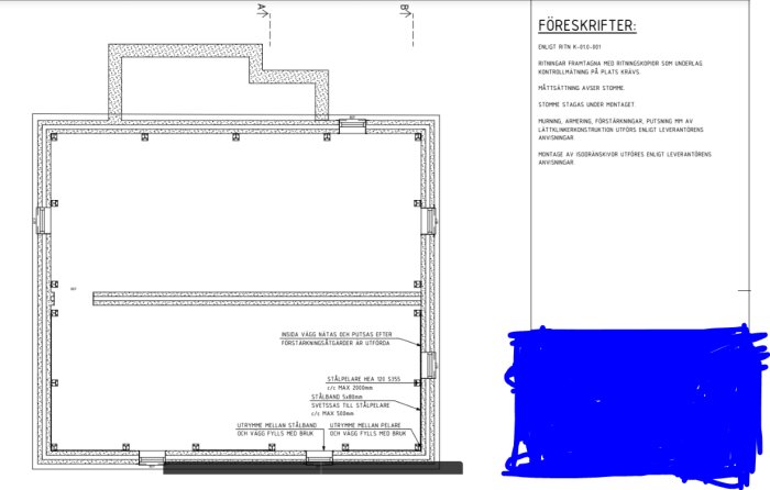
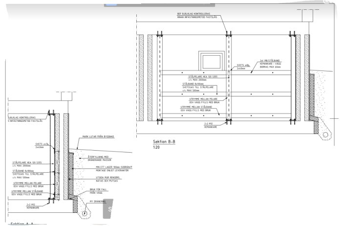
The walls in the basement of the house were so weak (started bowing) that we had to reinforce the walls to be able to perform drainage. Through our contractor (who will do the drainage), we contacted a structural engineer who came home, looked in the basement, and came up with a solution. I insert the result of the construction drawing which involves setting up HEA 120 beams around the basement to be welded together with a steel band (8x100 mm).
Now to the problems I've seen in this drawing....
1. In the upper left corner of our basement, there is a staircase that is not marked on the drawing where a steel beam is placed.
2. Half of the basement lacks a steel band (there should be a steel band sealed around the entire basement).
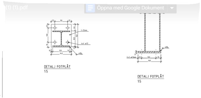
3. Spacer blocks (if that's what they are?) between the base plate on the steel beam and the concrete slab lack information about the material.
4. The space under the outdoor entrance stairs completely lacks steel columns, is there a collapse risk? since certain stones are missing in the wall where steel beams are supposed to rest.
5. There is no confirmed thickness of concrete, and no measurements have been done by the engineer, so how can the point loads be confirmed that are supposed to be supported by the concrete slab that comes from the steel column???
Point no. 5 is the one I see as most critical since the entire solution is based on the steel columns unloading the walls and taking the load both from above and from the sides. There should be a calculation regarding point load from the steel columns, and it should not exceed the maximum pressure the concrete slab can be subjected to?
I should add that this drawing cost us 43,000 SEK including VAT.
Additionally, I received a quote from the contractor for what the steel would cost. It landed at 111,000 SEK, which made me a bit contemplative. Is this reasonable? In total, it is about 20 steel columns HEA 120 S355 beams at 2m each, as well as about 93m of steel band (8x100m)?
I am writing a bit about the different points below. I list some assumptions below and how I assume the reinforcement is intended to function. I also assume that the basement walls are made of concrete.
I assume that the walls are bending inward due to horizontal earth pressure from the outside. I see this as the most reasonable explanation. If it were due to high vertical load, possibly the wall running through the middle of the room would also have bent outward. I can't see on the drawing what the upper space outside the basement is, but if that space is not filled with earth and the wall is not bending out along the extension, it also indicates that it is the earth pressure causing the outward bending. The outward bending can also be due to eccentric load from above walls. It looks like the wall on the floor above is situated quite far out on the basement wall, which gives an eccentricity that collaborates with the earth pressure.
The outward bending can thus have a variety of causes, but I assume that it primarily results from the earth pressure. Since the walls previously had sufficient load-bearing capacity and no significant changes have been made regarding loads against the wall (I assume that the surrounding earth is roughly at the same level as before, no new loads are acting on the floor slabs, etc.), the reinforcement will be an improvement compared to before.
I assume that the reinforcement primarily aims to strengthen against horizontal load. If it were to reinforce for vertical load from the floor slabs, there might have been a beam at the top between the columns to distribute load from the floor slabs to the columns. A concrete floor slab can distribute loads itself (see flat slab) but if one is not sure about the reinforcement in the floor slab (assuming it is a concrete slab), I would say that beams would have been added at the bottom edge of the floor slab between the columns. If the columns were to strengthen for vertical load from the walls above, they would need to be somewhat under the wall, but they are not, so I assume they are not intended to take vertical load from the walls above.
The columns should transfer the horizontal load up to the floor slabs and down to the foundation. These are the places where the horizontal load is currently transferred with the help of the basement wall, so there won't be any significant change in the load path other than the horizontal loads coming in a bit more concentrated at the floor slabs at the columns, which I think is okay. With the reinforcement, the loads will now be able to move up/down without stressing the basement wall as much.
The basement walls need to be able to transfer the horizontal load out to the columns (and then the columns transfer the load up/down as mentioned above), and this is what I think the steel bands are for. However, I am a bit doubtful about the function of the steel bands. It might be intended that the steel bands act like reinforcement and in that case, they need to be quite robustly fastened to the basement wall; I don't think 2 pieces of M8 can manage this. The steel bands might also work with linear tension (compare to suspension bridge). For linear tension, you assume that there should be some bending on the flat steel before they start to take load this way, and there will be a large horizontal load at the ends of the flat steels, and the only way to take this horizontal load will be through the columns' fastening in the roof and foundation; I am a bit doubtful this would work.
Even if the steel bands don't provide much addition to the load-bearing capacity, the wall is likely reinforced horizontally, which means that the wall can transfer some load sideways to the columns without the help of the steel bands.
1. The steel column needs to be connected to the floor slabs at the top and bottom, and if there are no floor slabs at the top, the steel column becomes inactive. If it is only the corner column that stands without a floor slab at the top, one could lay steel beams at the top to the next wall column to the right and downward in the plan drawing. Then the column will have support in 2 directions. If there are more columns lacking support at the top in that corner, it becomes a bit trickier.
2. Perhaps the designer intended for the lower part to mirror the upper part and therefore neglected to draw in the steel bands there, or the wall deflection was not as severe there, so it was assumed to work without the steel bands, or it could be an oversight by the designer.
3. There is no information about whether there should be any spacer blocks. If the floor is somewhat even, the plate can be placed directly on the concrete, but optimally (and a better execution) would be to inject the screws, put on the nuts, fit the columns, tighten the nuts until the column is vertical, leave 30-50 mm between the base plate and concrete, and then grout underneath the column, then put nuts on top of the base plate. Execution with grouting requires enough height to fit the column when the screws are in the foundation, otherwise, place the column, drill holes in the foundation slab and then inject through the base plate, but then there will be no nuts under the base plate, so one will have to shim it up in some other way before grouting.
4. Not entirely sure about which area/what this point refers to.
5. It's likely that the columns will not bear much vertical load, so the pressure on the foundation slab vertically might not be very significant under the columns. For the columns to bear vertical load from the structure's own weight, the floor slabs/walls must be jacked up before the columns are mounted and then unloaded so that the columns receive load from the structure. However, I think this is a bit excessive, assuming this won't be carried out. The columns, however, can take load that accumulates after their installation, such as load from people/furniture, etc. If one were to make a rough estimate, one could say that land, when not known much about, can endure 100 kPa in pressure (10 tons/m² / 100 kg/dm²). If the base plates were directly on the ground, they could handle 200-300 kg of load before the ground gives way. The concrete slab will also spread the load a bit, so if the base plate is on the concrete, it may handle 300-500 kg. Then there might be a risk of some settlement/cracks in the concrete, but it doesn't necessarily mean the ground doesn't hold. Hard to say much about this without knowing more about the reinforcement/ground conditions.
I'll write a bit about the different points below. I'll list some assumptions below and how I presume the reinforcement is intended to work. I also assume that the basement walls are made of concrete.
I assume that the walls are bending inward due to horizontal earth pressure from outside. I see this as the most reasonable explanation. If it were due to high vertical load, then possibly the wall running through the middle of the room would also bend out. I can't see from the drawing what the upper space outside the basement is, but if that space isn't filled with earth and the wall doesn't bend out along the extension, it indicates that it's the earth pressure causing the bending. The bending could also be due to eccentric loading from the walls above. It seems that the wall on the floor above is standing quite far out on the basement wall, creating an eccentricity that works with the earth pressure.
The bending can thus have a few mixed causes, but I assume it mainly results from the earth pressure. Since the walls have had sufficient load-bearing capacity before and no significant changes have been made regarding the loads on the wall (assuming the external soil level is about the same as before, no new loads affect the floor, etc.), a reinforcement would mean an improvement compared to before.
I assume the reinforcement is primarily intended to strengthen against horizontal loads. If it were to strengthen for vertical loads from the floor, one might need a beam at the top between the columns to distribute the load from the floor to the columns. A concrete floor can distribute loads on its own (see column-slab floors), but if you aren't sure about the reinforcement in the floor (assuming it's a concrete floor), I would say that beams would have been placed at the bottom of the floor between the columns. If the columns were to strengthen for vertical loads from the wall above, they would need to be somewhat under the wall, but they are not, so I assume they are not intended to take vertical loads from the wall above.
The columns are supposed to transfer horizontal loads up to the floor and down to the foundation. These are the places where the horizontal load is currently being transferred using the basement wall, so there won't be a significant change in the load path other than the horizontal loads will be more concentrated in the floor at the columns, which I think is okay. The loads will now be able to move up/down with the help of the reinforcement without loading the basement wall as much.
The basement walls need to be able to transfer the horizontal loads out to the columns (and then the columns handle the load up/down as mentioned above), and I think this is what the steel straps are for. However, I'm a bit uncertain about the function of the steel straps. Either the intention is for the steel straps to act like reinforcement, in which case they need to be quite firmly attached to the basement wall — I don't think 2 x M8 bolts will handle that. The steel straps could also act with cable action (compare to a suspension bridge). For cable action, it assumes there should be some bending of the flat steel before they start taking the load this way, and there will be a large horizontal load at the ends of the flat steel, and the only way to handle this horizontal load is with the columns' anchoring in the ceiling and foundation; I'm a bit skeptical that this would work.
Even if the steel straps don't contribute much to the load-bearing capacity, the wall is likely reinforced horizontally, meaning the wall can transfer some load laterally to the columns without the help of the steel straps.
1. The steel column needs to be connected to the floor at the top and bottom, and if there's no floor at the top, the steel column will be inactive. If it's just the corner column without a floor at the top, you could place steel beams at the top to the adjacent wall columns to the right and downward on the floor plan. Then the column will have support in two directions. If more columns lack top support in that corner, it becomes a bit trickier.
2. Either the designer might have intended the lower part to mirror the upper part and therefore ignored drawing in the steel straps there, or the wall bending wasn't as severe there, so it was assumed it would work without the steel straps, or it's an oversight by the designer.
3. I don't see any information about the presence of spacer blocks. If the floor is reasonably level, the plate can be placed directly on the concrete, but optimally (and for a better execution), inject the bolts, put nuts on, slip on the columns, screw on the nuts until the column is vertical, leave a 30-50 mm gap between the base plate and the concrete, and then grout the column, then put nuts on the top side of the base plate. Executing with grouting requires enough height to get the column in when the bolts are in the foundation; otherwise, you need to place the column, drill the holes in the foundation slab, and then inject through the base plate, but then you won't have nuts under the base plate, so you'll need to prop it up another way before grouting.
4. Not quite sure which area/what this point pertains to.
5. It's likely that the columns will not take much vertical load, so the load on the foundation slab in the vertical direction probably won't be significant under the columns. For the columns to take vertical loads from the structure's self-weight, the floors/walls would need to be jacked up before the columns are installed and then unloaded so that the columns bear the load from the structure. However, I think this is a bit excessive, and I assume this won't be done. The columns can, however, take loads that occur after their installation, such as loads from people/furniture, etc. If making an estimate, one could say that unknown ground conditions can withstand 100 kPa in pressure (10 tons/m² / 100 kg/dm²). If the base plates were directly on the ground, they could withstand 200-300 kg before the ground gives way. The concrete slab will also spread the load a bit, so if the base plate is on the concrete, it can withstand perhaps 300-500 kg. There could be a risk of some settling/cracks in the concrete, but that doesn't necessarily mean the ground isn't holding. It's difficult to say more without knowing more about the reinforcement/ground conditions.
Thank you for a detailed description and answer to the points I had! Really appreciated!
I will take that with me to the next conversation with the designer.
Another thought was that according to the drawing, the steel fittings should be drilled into the wall with chemical anchors. Instead of pushing the wall out, it tries to pull the wall inward? That sounds counterproductive, since we don't want the wall to be pulled in even more. Instead, perhaps wedges should be installed between the steel fittings and the wall so that it seems like the steel straps push the wall out?
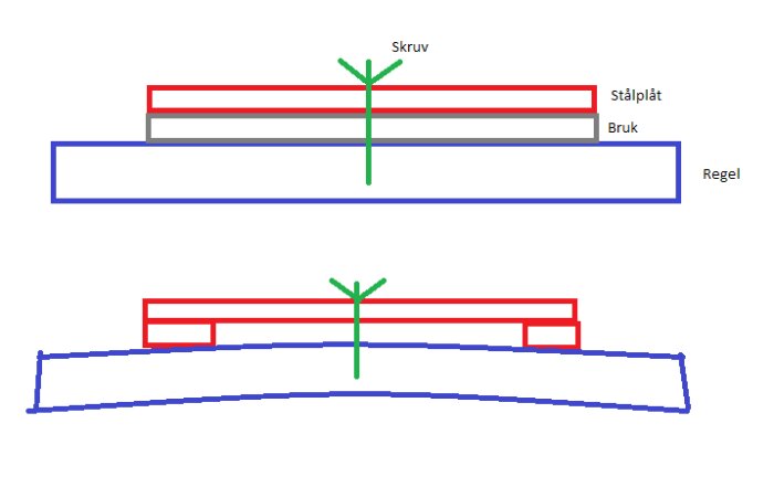
Hello, according to the drawing, the space behind the steel strap and the wall, as well as between the steel column and the wall, should be filled with mortar. If these spaces are filled with mortar and the mortar hardens before injecting and tightening the nuts, the wall will not move in any direction. It can be compared to the sketch below; if you screw a steel plate onto a beam with some spacer ensuring full contact between the plate and the beam, the beam will not bend in any direction. However, if the plate had been propped up with 2 smaller plates, the beam would start moving towards the plate when you tighten the screw. In this example, the wall is the beam, and the steel column/steel strap is the steel plate. The propping and air between the plate and the beam symbolize what happens if there is no contact between the wall and the steel column/steel strap.
Hi, according to the drawing, the space behind the steel band and wall, as well as between the steel column and wall, should be filled with mortar. If these spaces are filled with mortar and the mortar hardens before injecting and tightening the nuts, the wall will not move in any direction. It can be compared to the sketch below; if you screw a steel plate onto a stud with some spacers creating full contact between the plate and the stud, the stud will not bend in any direction. If the plate was elevated with 2 smaller plates, however, the stud would start moving towards the plate when you tighten the screw. In this example, the wall is the stud, and the steel column/steel band is the steel plate. The elevation and the air between the plate and the stud symbolize what happens if there is no contact between the wall and the steel column/steel band.
[image]
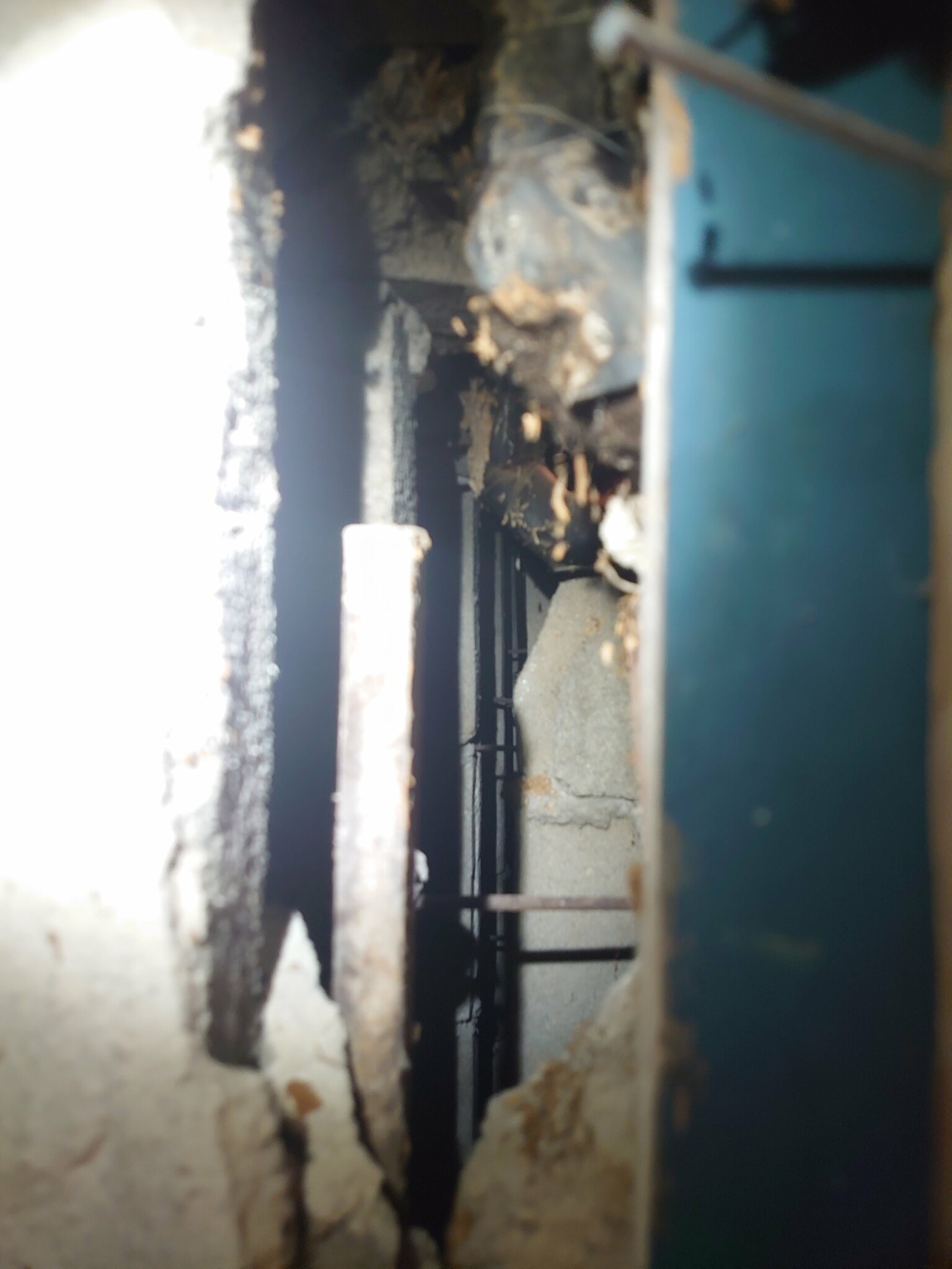
The builder was at our house this week... Unfortunately, he missed that we have an outer wall and an inner wall. This can be seen on the drawing. There is an air gap between the walls. See picture
Since the outer wall has collapsed so much that the inner wall has also started to give way, this solution, according to the builder, will not suffice. He admitted that he "thought" there was only one wall the basement consisted of. His suggestion now is to rebuild new walls instead...
Since we paid for a drawing that cannot be used, which was also based on incorrect assumptions, I am considering complaining and demanding our money back.
We have also incurred additional costs that we have already activated as a result of this drawing because we needed to reroute the district heating pipes as well as all the radiator pipes in the basement since the steel beams needed to stand along the wall.
Is it possible to complain about this, and is it reasonable?
Entirely reasonable to file a complaint. However, I won't comment on the outcome of that.
Unfortunate mistake by the designer, it's obvious they missed important parts they should have checked, as they were so critical to the entire solution concept.
They probably won't give in, because who willingly wants to refund a lot of money… Unfortunate situation
Perfectly reasonable to make a complaint. The outcome of that, however, I will leave unsaid. A disappointing mistake by the designer, it's obvious that they missed important parts that they should have checked since the entire solution concept depended on it. They probably won't give in, because who wants to give back a lot of money voluntarily... Unfortunate situation
Yes, "silver lining" is that we didn't order and start installing the steel pillars before we noticed this. Because that would have cost a lot more.
Strange that he thought it was just one wall when he himself had clearly drawn two walls with an air gap (which, by the way, should be indicated on the drawing).
Is the white part in the middle of the wall really an air gap?
If so, according to the drawing, the slab on the ground and the joist are also made of air.
Is the white in the middle of the wall really an air gap?
If so, then the slab on the ground and the floor structure are also air according to the drawing.
You are absolutely right!!!
That doesn't necessarily mean what I drew in the drawing above is an air gap.
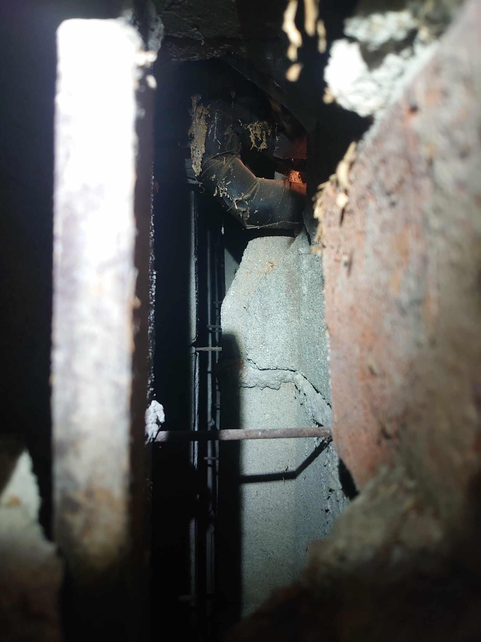
However, it is roughly how it looks in reality. Here is a picture taken of how it looks if you peek into the air gap through a door frame down in the basement.
Oh, it doesn't look good.
Has the designer overlooked how the wall is constructed? Then he hasn't found out the conditions for doing his work. It's not a small detail that was missed.
And since the measure proposed by the designer cannot be used, the work is wasted. And the designer has probably not delivered what was requested.
Regarding your other costs incurred due to performing preparatory work to use the designer's solution. (Relocation of pipes, etc.), for those costs you should direct a claim for damages against the designer.