I am wondering how to calculate the load-bearing capacity of two vertically nailed together joists.
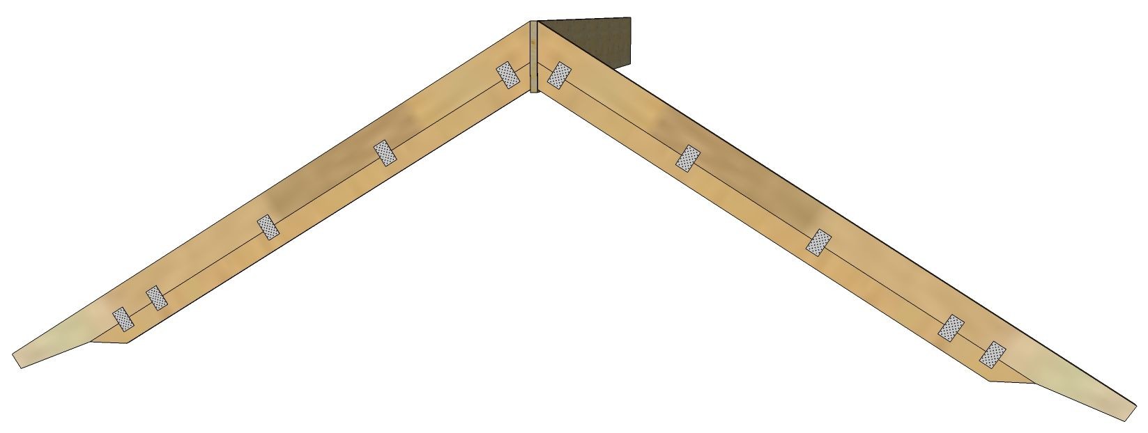
On the website belonging to a carpentry factory near Arlanda, there is a picture of what they call a "Ryggåstak" where you can see two joists nailed together with nail plates (or nailing plates). Can you fully account for the load-bearing capacity in the combined cross-section, e.g. 2 pieces of 45x170 = 1 piece of 45x340, or is it more complicated than that?
I'm also wondering if there is any reason why the nailing plates are positioned as they are – thinking in terms of reactive load nodes, etc.
No, I realize that. But doubling the height of the beam increases the moment of inertia by 8 times, and I had hoped that one could account for some increased load-bearing capacity with the extra beam. But then you would need to be able to calculate joints using nail plates and that's advanced for me...
I don't actually think there is much difference between spliced and solid joists. The strength is not in the middle but in the outer edges. Compare with, for example, HEA beams, where the flanges provide the strength, not the thin web.
When the beam is loaded by the roof pushing downward, the top side will compress, while the underside will want to stretch out. The middle of the beam, where the splice is, will for symmetry reasons not have any stresses at all.
That's what I think... It's been a loooong time since I studied Structural engineering.

I would rather have glued the halves together with PUR glue and clamped the joint with clamps during drying time.
But otherwise, mycke_nu is right in their reasoning.
But otherwise, mycke_nu is right in their reasoning.
I will let truss manufacturers, for example, "near Arlanda," put together the trusses to avoid discussions with the building permit officer. It can be nice to have documentation on the trusses. Currently, I am drafting the house. The floor plan dictates the construction and everything related to it. I am using the full version of Wood Express from Runet in Norway to try to "get it right" in my assumptions. The program follows Eurocode 5 and is updated regarding snow loads in more local conditions for the area where I intend to build. However, the software cannot create composite rafters in the way I desire, but you can trick it by entering custom dimensions for the timber. It is then calculated as homogeneous beams, which it is not unless you switch to veneer or glue-laminated timber, which is not the case here. Securing against tipping with chipboard on the upper side and cross bracing on the underside of the truss. I really appreciate all the responses...
Click here to reply