Amateur carpenter here, working on building a workshop area in our old barn. The floor is cast, a folding door is installed, and now I'm planning to start building a ceiling. Right now it's completely open all the way up to the ridge.
But I'm pondering how to best construct the ceiling.
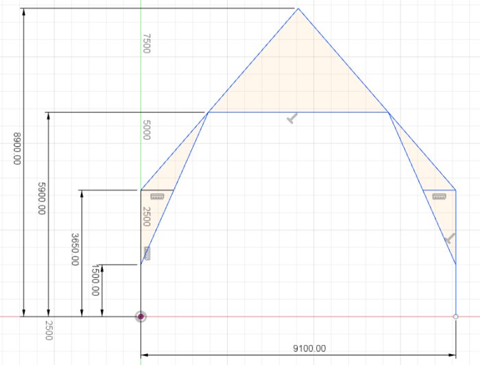
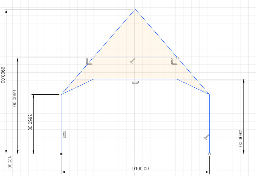
Below is a sketch of how it is currently constructed. It is about 250cm between each span, and it's built with square timber of 5-6 inches. Snow zone 2.0 where I live, and the roof is metal if that's of interest.
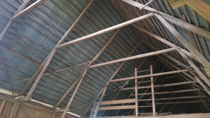
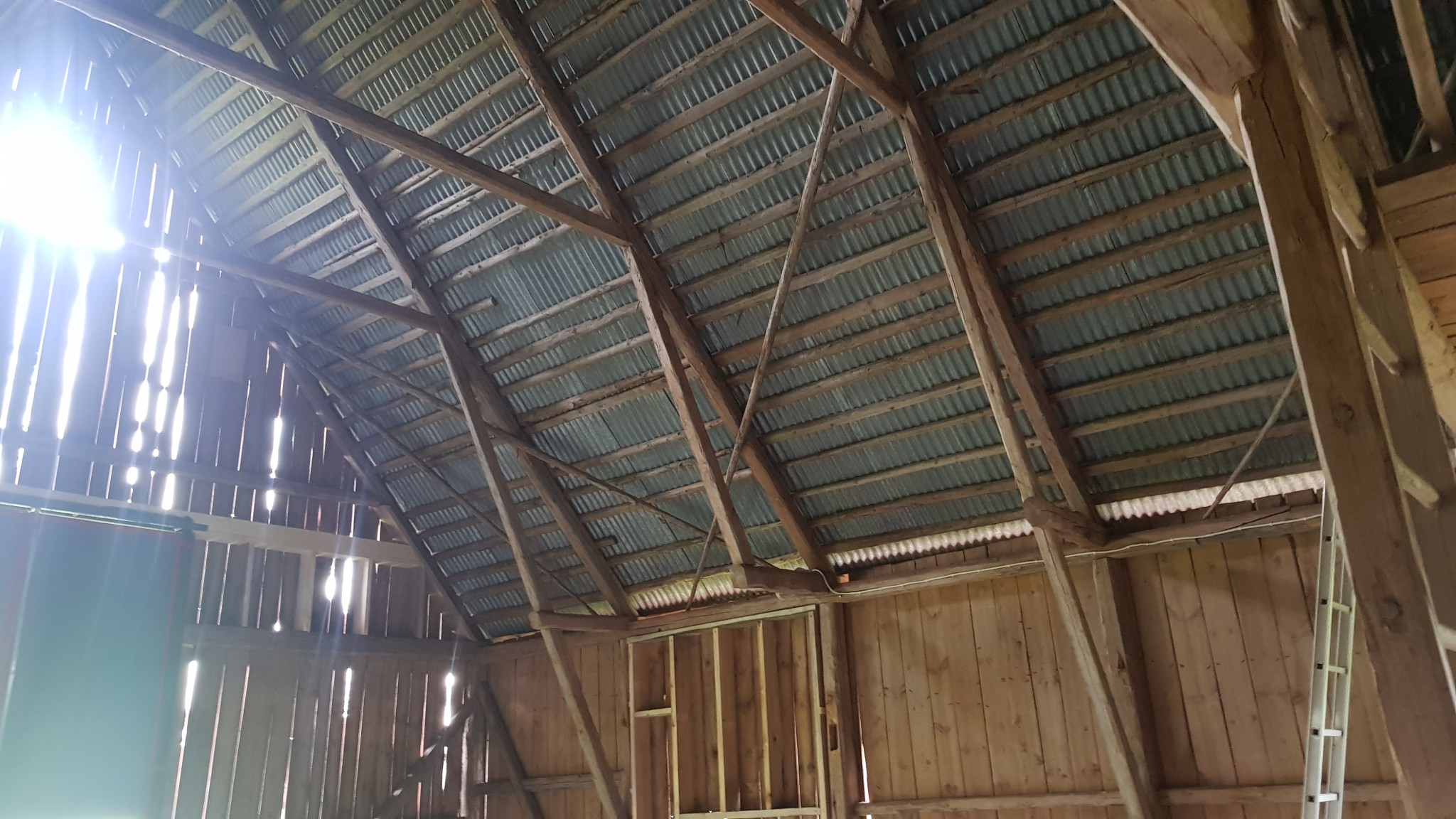
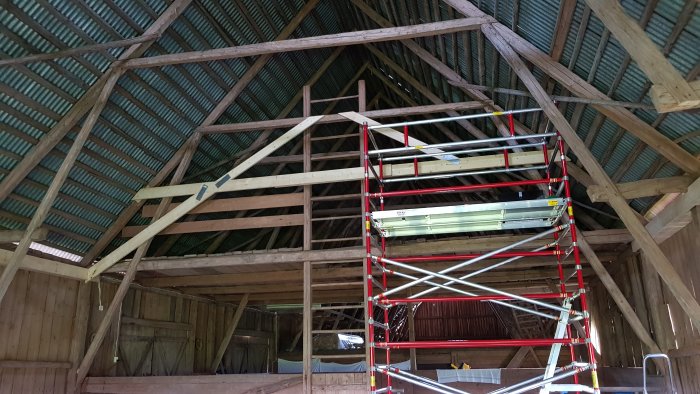
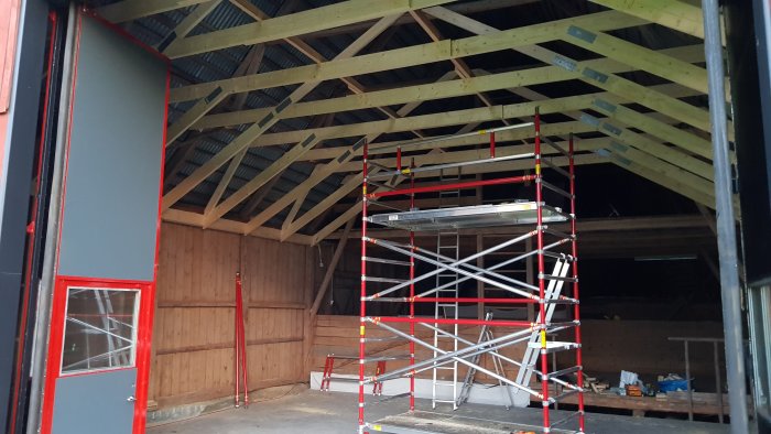
Also a couple of photos of how it looks today:
I'm planning to set the ceiling height at 460cm, so it's just over a meter below the existing "beams." The new ceiling will run from the gable to the ladder visible in the first photo, just under 10m long. A lot of weight to go up in not so much timber, so it clearly needs to be reinforced a bit. The diagonal braces that run down the wall also take up quite a bit of wall space (can't put shelves, machines, etc. there), and it would be nice to get rid of them. They certainly bear a lot, but there are only two on each side that need to go as one is already missing....
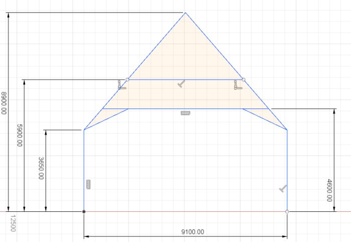
I'm considering something like this. Basically, removing the existing diagonal braces and making new ones that start on the wall and go a little further onto the inner ceiling. It should probably be reinforced with some braces up to the trusses as well. But do you think it would work? And tips on what these reinforcements could look like?
It will also be twice as densely studded as now (the sections are, as mentioned, about 250cm, so I'm thinking of studding cc125 or so, basically a new one in between. I'm thinking of using 45x190 C24 timber. The beam will be about 750cm long, so there will have to be a joint in the middle. I think it would be good to take two 460s and screw them together at the overlap in the middle (it won't be completely straight when you do that, but nothing is straight in this build anyway). Then followed by spaced paneling cc30 and three layers of sheet material (1x OSB + 2x gypsum), should meet EL60 to satisfy the insurance company.
Drew a bit better and utilized the simulation part in Fusion 360 (never used it before).
Numbers are uninteresting since the entire simulation is done with steel as the material, wood isn't available as an option. But relatively, comparisons can be made.
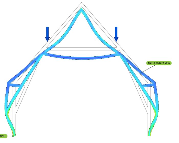
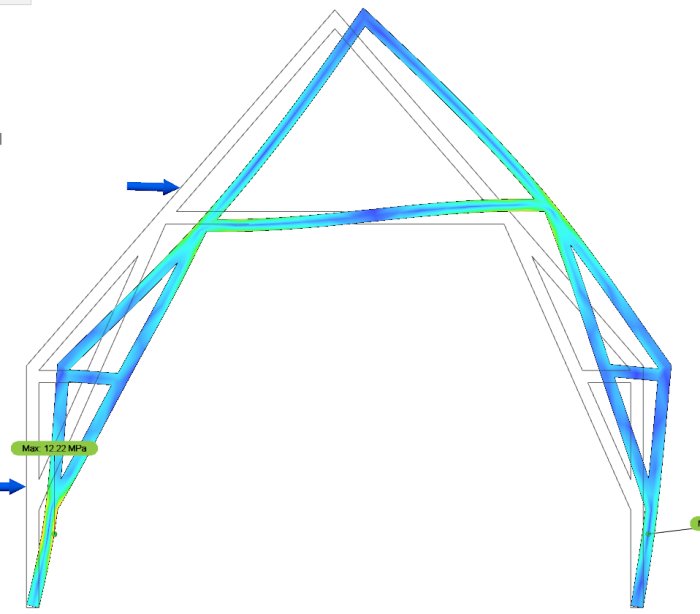
Here's how it looks with the load on the roof with the existing construction:
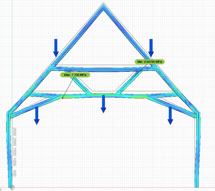
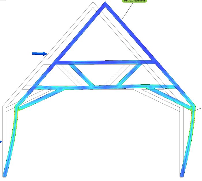
And my proposed new construction, where I added a couple of extra reinforcements upwards, and then hung quite a significant weight downwards (the weight of the inner ceiling) as well as the same weight on the roof. This shouldn't pose any problems...
The simulations here do not consider that the screw joints may not have the same strength as the material otherwise, but it's hard to believe it would be a major issue when it looks so *much* better...
It's an interesting project you have in mind. It should be possible to input different values for the modulus of elasticity and the moment of inertia in the simulation program so that the result instead resembles wood. 6x6 inch lumber is stable material with the same stiffness both horizontally and vertically. As a beam, a 6x6 inch log corresponds to a 2x9 inch joist. However, I am skeptical about your solution for both practical and theoretical reasons. I believe more in a completely independent construction in glulam. It will certainly be much faster to build it.
It's possible to create custom materials, but it requires a ton of parameters. There actually is pine to choose from, but it doesn't work to simulate with for some strange reason. I can try to fiddle with it some more, but it's still difficult to get reliable numbers through simulation when you don't know exactly what you're doing. Easy to fool oneself somewhere, so I mostly found it interesting to see the sheer difference compared to how it has been described up until now.
When you say "completely independent structure in laminated timber," do you have any suggestions on how such a structure could look?
Surely the beams at a height of 3650mm must have gone from wall to wall when it was built? The ones that only have short stumps remaining today. As an amateur designer, it's fun to see that computer simulations behave roughly as one imagines the forces in a structure. The person who cut those beams should have realized the catastrophic impact it has on the structure. Regarding your new design, I would have wanted the joints closer together. Less bending moment.
Surely the beams at 3650mm height must have gone from wall to wall when that was built?
Those of which only short stumps remain today.
As an amateur constructor, it's fun to see that computer simulations behave roughly the way one imagines the forces in a structure.
The person who cut these beams should have realized the catastrophic impact it would have on the structure.
Regarding your new construction, I would have wanted the nodes closer together. Less bending moment.
Actually, they probably never were whole, but have likely always been as they are. In a small section of the barn, they are whole, the part that you might glimpse in my photos. Further away in the barn, it is built lower, but then new studs have been placed from wall to wall lower than that (those stumps also exist there, up in the loft).
Nodes closer together, exactly what are you thinking of then?
I believe that the "cut beams" have always been cut. The primary function of the diagonals has been to stabilize the high walls. A not entirely uncommon construction.
A glulam construction consisting of columns and beams placed in the sections between the existing roof structure is quite simple to achieve. On the beams, you then lay a secondary framework of regular construction timber. As an estimate, you can use 115x540 for beams and 115x115 for columns. As floor joists across, 45x170 C 24 should be sufficient. You can adjust to the desired height, but when you go beyond the top edge of the wall, the columns will end up a bit into the floor.
Ok.
Yes, now it was quickly drawn freehand, but I'm thinking something like this:[bild]
Or something in between... it might not work practically.
The problems I see immediately with those two are that on the left one, you lose a lot of ceiling height. On the right one, you have a much longer span in the middle of the lower horizontal beam that should support the ceiling's weight, a greater risk of it sagging in the middle (whether that's actually a problem, I'll leave unsaid, though).
Jjustusandersson said:
I believe that the "cut beams" have always been cut. The primary function of the diagonals has been to stabilize the tall walls. A not entirely uncommon construction.
A glue-laminated timber structure consisting of columns and beams placed in the spaces between the existing roof structure is fairly simple to achieve. On the beams, you then place a secondary support structure of standard construction timber. Roughly, you can use 115x540 for beams and 115x115 for columns. As floor joists across, 45x170 C 24 should be sufficient. You can place it at the desired height, but when you go above the wall's top edge, the columns will end up a bit into the floor.
Are you basically thinking that a column in each corner would suffice in that case? Because several in the middle wouldn't be fun since they would end up in the middle of the floor.
And do you think 45x170 can hold the ceiling's weight without any support in the middle? We are talking a span of about 7.5 meters.
Then it seems like you would need something to replace the function of the diagonals if you're going to remove them; you don't get that automatically in the construction if I understand you correctly.
I amused myself with some more simulations.
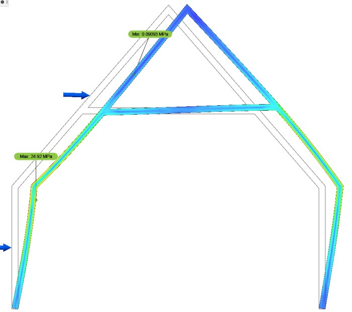
There is no doubt that the diagonals are beneficial for the sake of the walls; if you apply a bit of side force (a strong gust of wind), they come into their own.
There's not much visible difference in how much the material actually moves in the simulations, but what is interesting is where the forces are located. With the diagonals, there is very little twisting force where the roof truss sits on the wall, whereas without them that's where *all* the force goes.
With my suggested compromise, with a smaller diagonal brace, some of the force has clearly been moved away from there at least.
Started building now, roughly following my idea that I showed here. But I changed the upper diagonals as Bjober suggested so they align with the lower ones. It felt very stiff in the middle, so I don't think any direct reinforcement is needed there as I initially thought.
It feels like it will be both stable and feasible to implement.
Didn't get very far in one day; it took a while to figure out how to do everything. But now things should start to move a bit more smoothly.
It might not be relevant, but what does the insurance company say about this homemade construction if it were to collapse in the next storm?
Because you do want the building/workshop insured, right?
This might not be the right place, but what does the insurance company say about this DIY construction, in case it collapses in the next storm?
Because you do want the building/workshop insured, right?
I am as much an amateur as you are, and apparently so is the thread creator.
But if it were my building, I would hire a structural engineer to have the construction checked.
Vi vill skicka notiser för ämnen du bevakar och händelser som berör dig.