I'm in the process of tearing out the upper floor of my old log house. The plan is to open it up to the ridge.
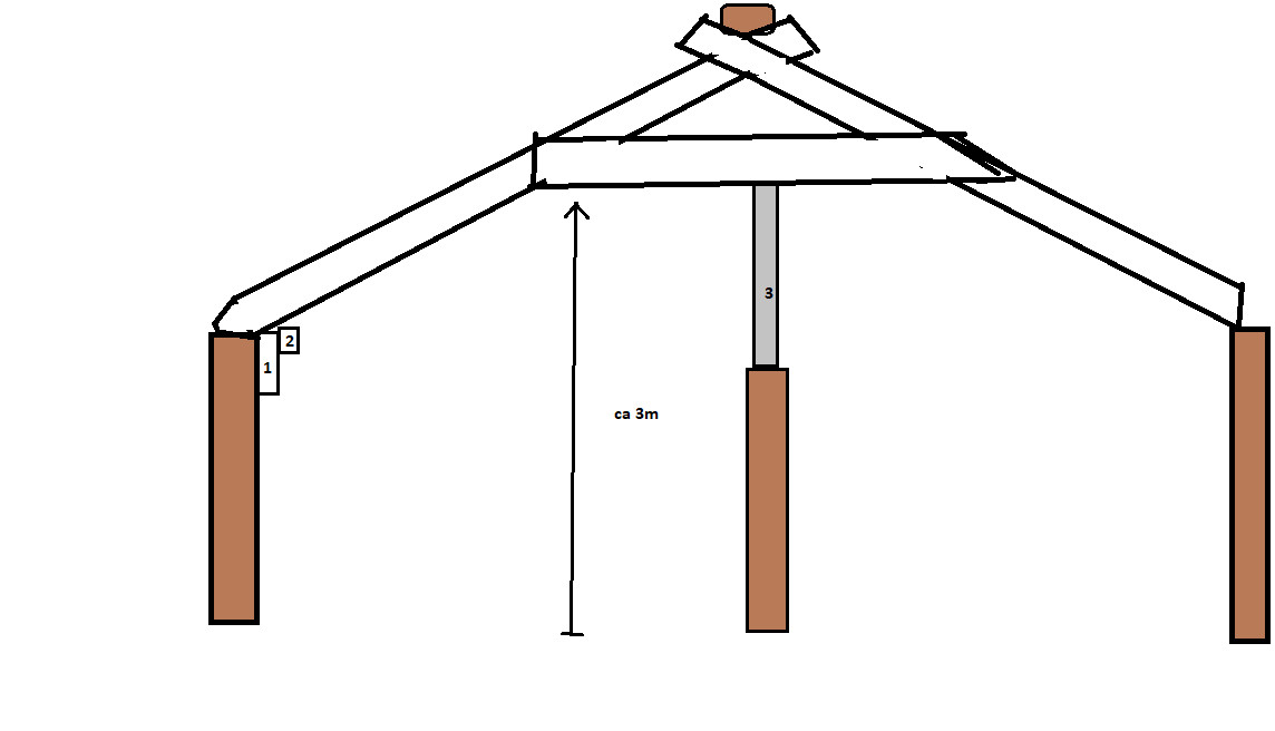
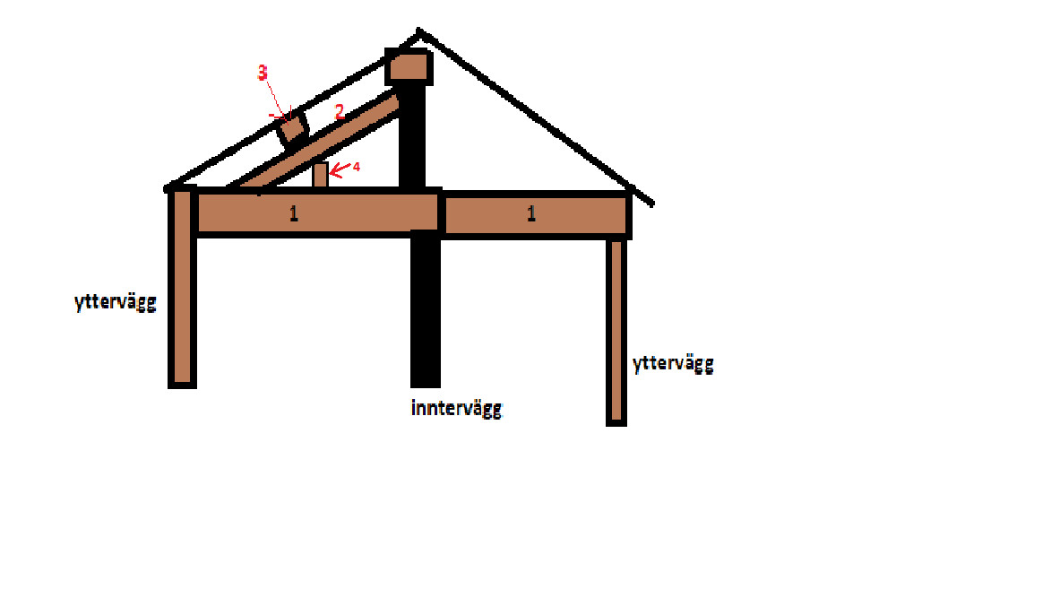
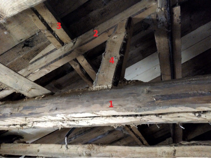
Two of the rooms in the middle have a beam running right through them to the middle of the wall that separates the rooms and aligns with the ridge, kind of like n1 in the figure below. On this beam, a post (no. 2 in the image) runs from foot to ridge, providing support to the post (no. 3) that goes in the same line as the ridge and outer wall. There is also a small piece no. 4 in the image going down to the beam to give better support to post 2.
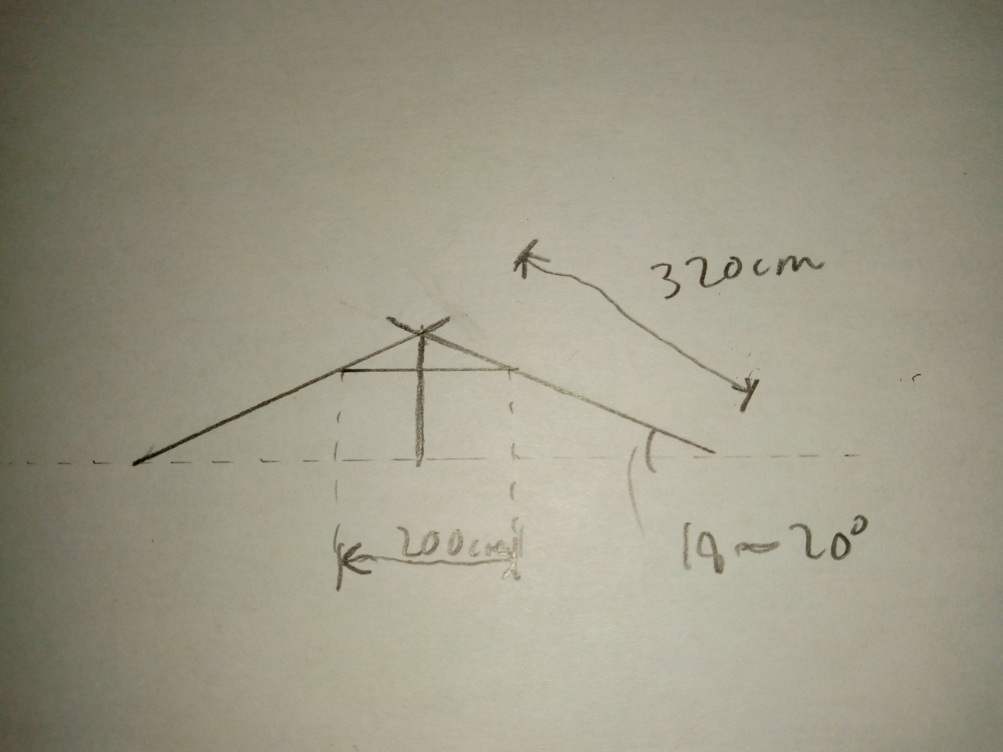
The room spans 4.6m and thus has this beam in the middle of the room. Post no. 2 is about 125x55, as is post no. 3, although post no. 3 is made by nailing together two 125x55 posts. The roof slope is maybe 15-20 degrees.
I would obviously like to remove beam no. 1, and the question is what would be sufficient as a replacement. It does feel a bit weak as it is now, to say the least, so it shouldn't be too difficult... but I see 2 options
1. Frame up cc 60 with A trusses (which I will do anyway from foot to ridge where the foot will rest on a beam screwed into the timber and rest on the timber). I would prefer to use 145s here, though I can go with thicker ones if necessary...
2. (Do 1 anyway with 145s, but it might be too weak...) Add a glulam beam next to beam no. 3 that spans the entire room. The dimension of this is highly unclear... The A trusses I build from the interior ceiling can also support this.
(Additionally, I will insulate with cellulose boards without an air gap, vapor open principle)
What I'm aiming for is to dimension sufficiently oversized to be safe... This roof has stood firm since 1940 (when a roof lift was done on this part, the house is otherwise from 1826...) so the construction holds as it is. The only thing I want to replace is what 1 and 4 contribute. I won't hire an engineer to calculate anything; instead, common sense and reasonable exaggeration will prevail.
Hmm, your approach to this might not be correct; just because it has held since the early 20th century doesn't mean it will hold if I remove the beam that holds everything together... not quite.
It's difficult to know exactly how they constructed this, but one thing that is 100% clear is that the bottom beam holds the outer wall in place.
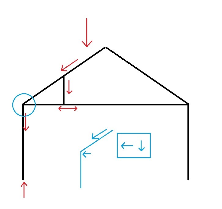
We'll continue with sketches in paint because they are so obvious and can't be misunderstood.
The force comes down into the truss and is distributed to the outer wall and the bottom frame.
A force applied at an angle can be broken down into components, which means you should have resolved the attachment of the outer wall and plan for the bottom frame to hold the outer walls in place, so the roof + walls don't do a Bambi on ice, i.e., lie down.
Possibly you have a chimney that holds a bit, but if you are going to take up the load from the roof without pushing out the wall, you should get a beam in the bottom edge and then attach it to the bottom frame that you are not removing. So this load has somewhere to go.
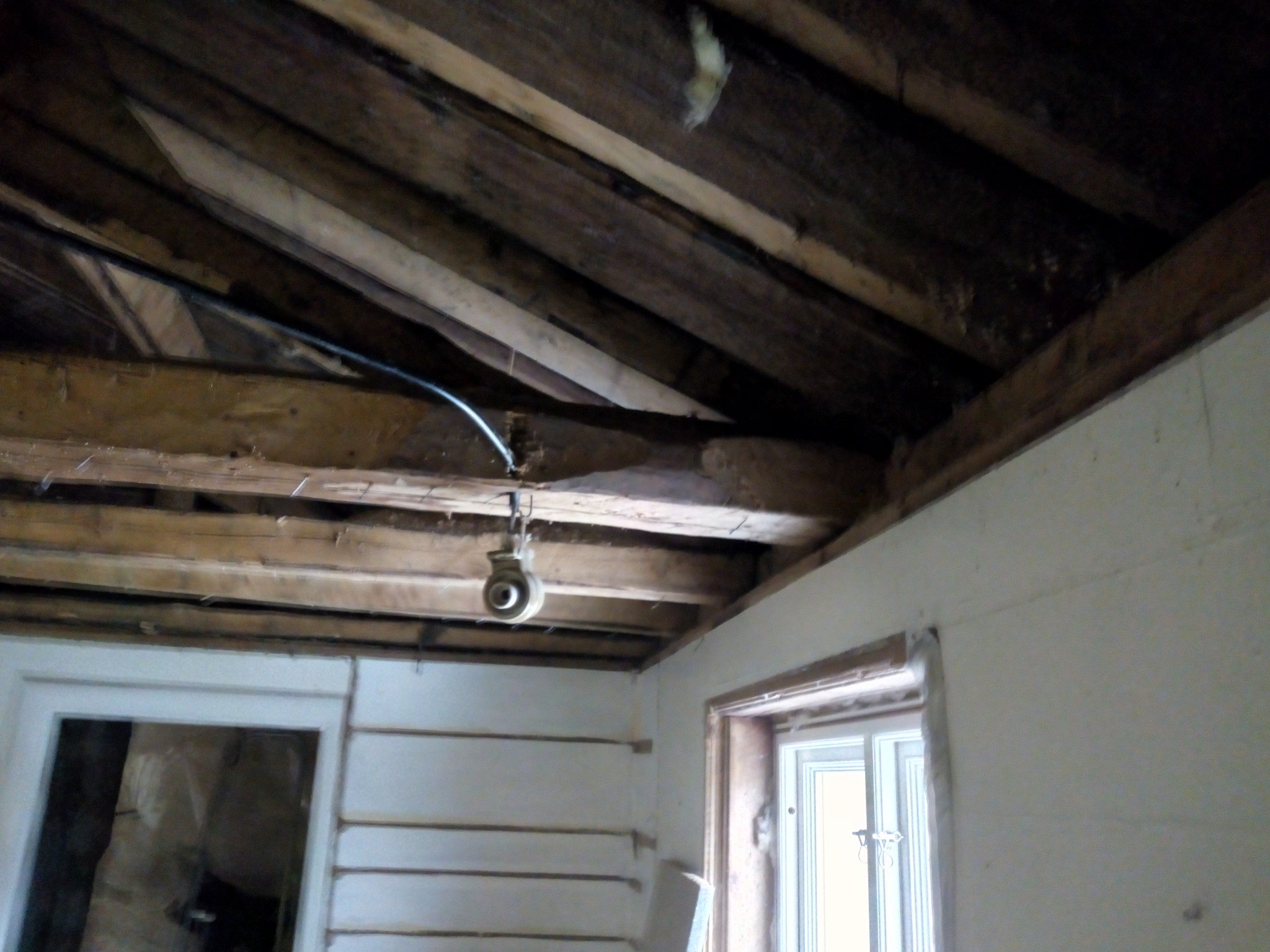
It is not quite possible to understand how the entire roof structure looks and functions based on the picture and your descriptions. Please attach more pictures and sketches.
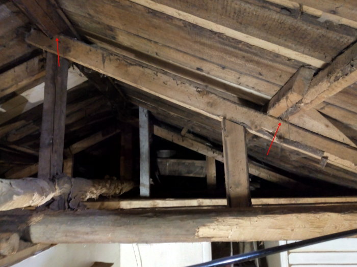
I find it difficult to get an overview of the problem. However, certain conclusions can be drawn from the photo. Since the roof boards are aligned with the slope of the roof, beam no. 3 acts as a ridge. How does it look on the other side? As @pjapen points out, beam no. 1 functions as a collar tie, meaning it holds the long sides together. It's strange that it seems spliced in the middle.
In general, a solution with a ridge beam and rafters works best if you want to open up to the ridge. Without knowing the house's dimensions, nothing can be said about suitable dimensions. Beam no. 1 could be replaced with a steel tie rod. With a ridge beam, it might be excluded if the long sides are sufficiently rigid at the top. However, this should ideally be assessed on-site.
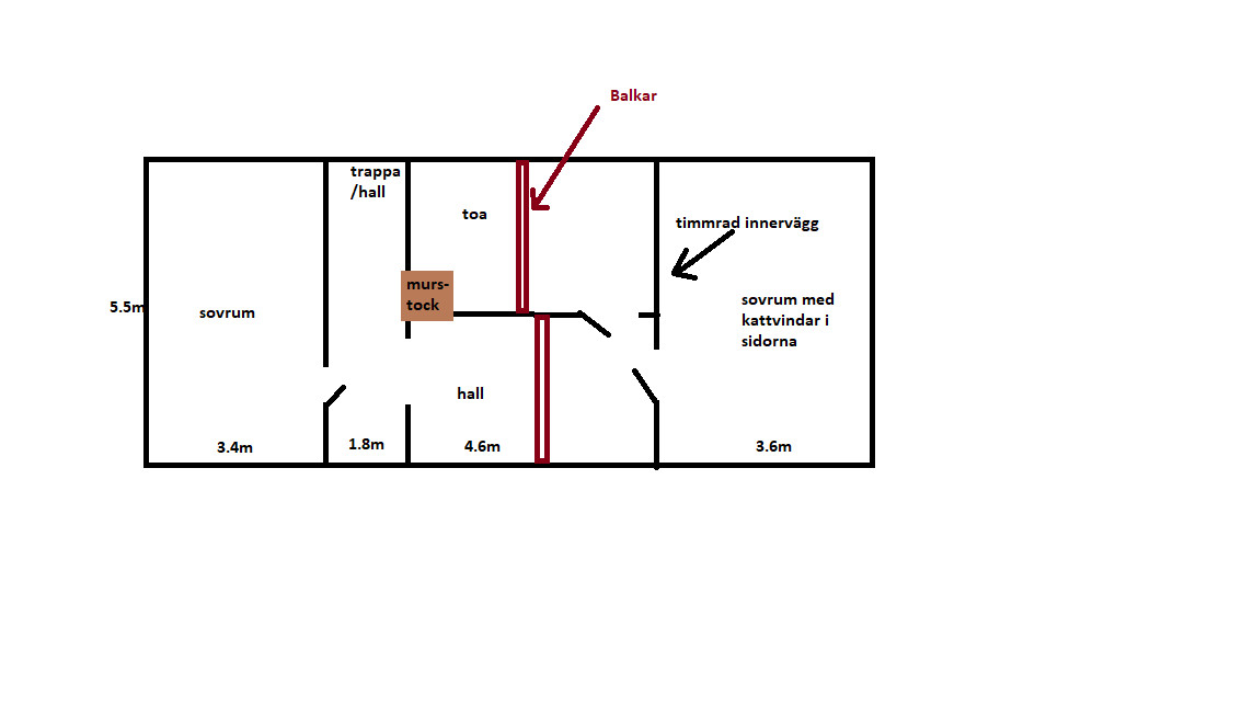
Incredibly thankful for all the responses! I'm going to take more photos today after tidying up a bit more as it was difficult to get a good picture yesterday. I sketched a drawing that gives a better idea of the house's structure. The roof was raised in the middle sometime in the 1940s and encompasses the entire middle section of the house. The partition walls to the bedrooms should hold the house together. Then I'm not at all looking to remove this beam without replacing it with something.
So it's about removing ONE of these beams through the house. If I install new rafters according to my other fine sketch... where 1 is an arbitrary longitudinal 45x145 or similar that is screwed into the timber and 2 is a longitudinal 45x45 glued-screwed into 1 and screwed up into each rafter, then it should strengthen the exterior walls. If these are also set at 60 cm intervals through the room, my hope is that they will be able to replace the current beam.
I might also consider keeping the beam in the hallway and only removing it in the bathroom just in case.
Worth mentioning is that the outer roof, which is firstly made of lock plank from eaves to ridge, has 45x45 battens from eaves to ridge (for leveling the roof and to be able to lay a breathable membrane). As purlins, I have 45x70 and last but not least, tiles, not concrete.
I interpret it as you want to open up to the ridge at the middle part of the house. The roof construction requires some form of beams to support the roof boards in the middle. The truss-like structures currently serve the function of supporting the beams. If you replace the beams with glulam beams that can span the entire middle section, you can remove these structures. I am not quite sure how it looks at the ridge. You probably need a glulam beam there as well.
I will open everything up and have already done so at one end of the house. There was nothing after I tore it down that had to do with load-bearing. Now I am at the middle section of the house where there is a 20-degree roof pitch.
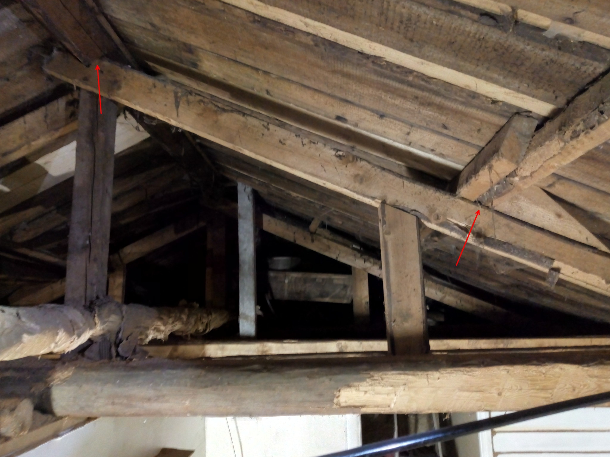
The only thing I want to do is remove one of the beams that spans from the long side to the long side of the house. I find it hard to understand that this would contribute to the load-bearing capacity for the walls and roof equivalent to various laminated beams. Here is another picture.
The function of this half truss is to support ridges and ridge beam. See the red arrows. If you remove the truss, the roof will collapse. If you replace the ridges and ridge beam with glulam of the correct dimension capable of spanning a longer distance, you can remove a truss without any issue.
I should not remove any rafters but only the beam that goes from the outer wall horizontally to the middle of the house, preferably on both sides of the central wall. I will also frame up with new "rafters" cc60 for the insulation compartments. These will go up to the ridge, and I can also let these have support down to the central wall.
If only the roof beam consisting of 2 nailed together 55x125 can be made sufficiently stiff, it should be possible to remove the underlayer.
If this single "truss" that supports the joint of the ridge is also complemented by more trusses/joists supporting the ridge, the load is distributed so that each part only needs to take a fraction of the load that the current construction takes. (X = number of trusses/joists.)
Whether the outer walls are sufficiently stiff to manage without the binding of the underlayer depends. One would need to know more about the construction of the entire wall section. Those joists appear to be original timber frame, so they might be crucial for the outer wall's stability. If it is a real problem, it should also be possible to solve with alternative construction to today's.
If, for example, Justus gains clarity about the construction of the house's midsection in its entirety with measurements and dimensions, as well as the state of the outer walls, he can surely propose good solutions.
The partition wall consists of vertical planks. The exterior walls in this part of the house have vertical logs with a height of 1.2m resting on the old horizontal log frame. On top of these is a horizontal log and then the roof.
My plan is to install new prefabricated A-trusses cc60, which will be screwed into the top log and lie under the longitudinal nailed 125x55 batten and up under the ridge. I can also add a brace down to the partition wall. These should contribute more to keeping the walls together than a horizontal log, right? I also plan to dimension by screw-gluing 2x145s in each A-truss for extra security
(Outside the bathroom wall, there is a patio set up with glulam beams 3.6x7.2m. The long glulam beam that is attached to the house is screwed into the top original log, which is about 1.5m from the eaves; this might be irrelevant in the context....)
See fig. for the sketch of intended trusses. Since I will frame up 45s on the interior walls, I plan to place a longitudinal batten on which my trusses will rest (as well as resting on the exterior wall's log). On this batten, I will screw-glue a 45x45, into which I will then drive a screw from underneath straight up into my truss batten. This should keep the exterior wall in place, right?
")