4,373 views ·
14 replies
4k views
14 replies
Reinforcement of floor structure - have I calculated correctly?
I have a 170-floor structure that is framed CC60 with a span of 2.7m
That is, already on the weaker side.
To avoid having to step up into my new bathroom, I’m considering lowering it further.
The floor inside the bathroom will be approximately 22mm chipboard, 12mm piping, and 25mm leveling compound at the highest point plus 15mm waterproofing/adhesive/tiles = 74mm over the floor structure.
The floor outside the bathroom will then be approximately 22mm chipboard, 15mm-25mm surface floor (parquet or ceramic in the hallway). = 37-47mm over the floor structure.
By lowering the floor 35mm, I thus get roughly the same or a lower level in the bathroom as outside.
To solve this, I have considered attaching reinforcement in the form of 10x120mm flat bar on the side of the joists, at the bottom towards the basement.
In my calculation, I have the following input values.
Allowed deflection l/300
Total useful load and weight 3kN/m² = 1.8kN/m distributed load for CC60
E-module for steel 210Gpa and for C24-lumber 7.4Gpa
With l/300, I find that the required moment of inertia is 72.7mm^4 for steel and 2063mm^4 for wood.
I find that I = 1842mm^4 for a 45x170 joist and that I = 144mm^4 for a 10x120 in steel.
The conclusion is that a 170 joist is indeed too weak, but that a 10x120 bar in steel can handle the task on its own and can even manage l/600 at the current load.
By taking advantage of the 45x135 that remains from the joist to reinforce the steel plate against buckling, as well as the extra bending stiffness that remains, this should therefore be an adequate solution from a bending stiffness perspective if I have calculated correctly.
Have I?
And as question 2, am I unnecessarily fixated on avoiding stepping up on the bathroom floor? It can be mentioned that the floor structure is already open, and the measure feels reasonable as long as it is technically sound.
Last edited:
Some calculation comments:
It looks like you've used cm in your calculations.
I for a 45mmx170mm is 1842 cm4, and I for a 10mmx120mm is 144 cm4.
The required moments of inertia I get are 65.9 and 1870 cm4, respectively (about a 10% deviation from your figures).
It looks like you've used cm in your calculations.
I for a 45mmx170mm is 1842 cm4, and I for a 10mmx120mm is 144 cm4.
The required moments of inertia I get are 65.9 and 1870 cm4, respectively (about a 10% deviation from your figures).
I know I'm late to the game, but if you are to calculate entirely according to the standards, you should include some partial coefficients on the load side as well. 0.91 x 1.2 x self-weight + 0.91 x 1.5 x imposed load. Then your design line load on the floor joists will be slightly larger.
You might need to rethink this...D David_Berglund said:
You need at least 12-13mm above the pipe at the lowest point, which means around 50-60mm leveling compound where it's thickest.
I wrote before thinking it through. The above applies to failure. Not for use and deflection. Just disregard that. However, it's good to check that case too..!Mackan87 said:
I calculated 12mm on the pipe and an additional 25mm at the highest point = 37mm self-leveling compound.nino said:
I might need to add another 10mm to that number for some margin, you're probably right, but I think you misunderstood my summary otherwise...
Or please correct me if I still need to rethink.
When you have chipboard flooring and reinforce the joists with self-leveling compound, the minimum is 12 over the chipboard, or if it’s 13mm, at the lowest point.
If you have water-based heating, you start measuring from the top of the pipes and go up 12mm, meaning pipe 12mm + 12mm self-leveling compound.
If you then have a shower with a floor drain, you should have a local slope, which is usually 10-15mm, and then you should have a slope over the entire floor towards the drain, about 1:100, so depending on the distance from the drain to the furthest point, you have an additional 10-20mm.
12+12+12+20=56mm
Pipe + minimum compound + local slope + floor slope
https://www.gvk.se/branschregler/golv/golvlutning/
This is what I have adhered to, and considering that I have 1.9m as the longest distance from my shower area, I can settle with 10-15mm.
But I realize that I need to add some extra height for the localized slope, so thanks for pointing me in the right direction.
The most important thing was to verify that I am not making a fatal mistake in my calculations on the loads. I can also live with the finished floor being a few centimeters higher than the surrounding floor, but it's very disheartening with 4-5 centimeters higher.
Right now I'm considering lowering the boards and placing them on supports between the beams. My carpenter says this is fairly common, and the floor is lowered by 22mm relative to not doing so.
I'm considering whether this compromise might be a feasible way to not make a mountain out of a molehill.
I also have an option where I'm considering casting a free-bearing arch of EPS concrete on composite metal decking, and have been promised calculation help on this solution by tomorrow. In this case, I cast the pipe in and can settle with 15-20mm of leveling compound in total by roughly shaping the slope in the concrete. It might be the most uncompromising alternative. As I save on leveling compound, the relative cost is not that much greater, but it's quite a bit more work.
No, I agree.
I brought this up with the carpenter who suggested the concept, but he mentioned that with reinforcement/mesh in the leveling compound, it becomes almost self-supporting in itself, and that this effect outweighs.
But of course, he is not a distinctive expert on this specific matter, but he has built a number of houses where they have done this.
Any opinion on the EPS-cement path?
Well, it's a good method, a bit expensive but it may be worth it sometimes.
I don't remember exactly but isn't it the 170 rule if you're going to use it in a bjälklag? Then plywood at the bottom, a bit unsure as I've mostly had it on concrete slabs.
I don't remember exactly but isn't it the 170 rule if you're going to use it in a bjälklag? Then plywood at the bottom, a bit unsure as I've mostly had it on concrete slabs.
The idea, in that case, is to cast it on Peca-45 composite sheets, which should allow for a thickness of 130mm.
I have been promised calculation assistance during the day, and have raised the question in a separate thread. https://www.byggahus.se/forum/threads/samverkansbjaelklag-med-eps-cement.479898/
I have been promised calculation assistance during the day, and have raised the question in a separate thread. https://www.byggahus.se/forum/threads/samverkansbjaelklag-med-eps-cement.479898/
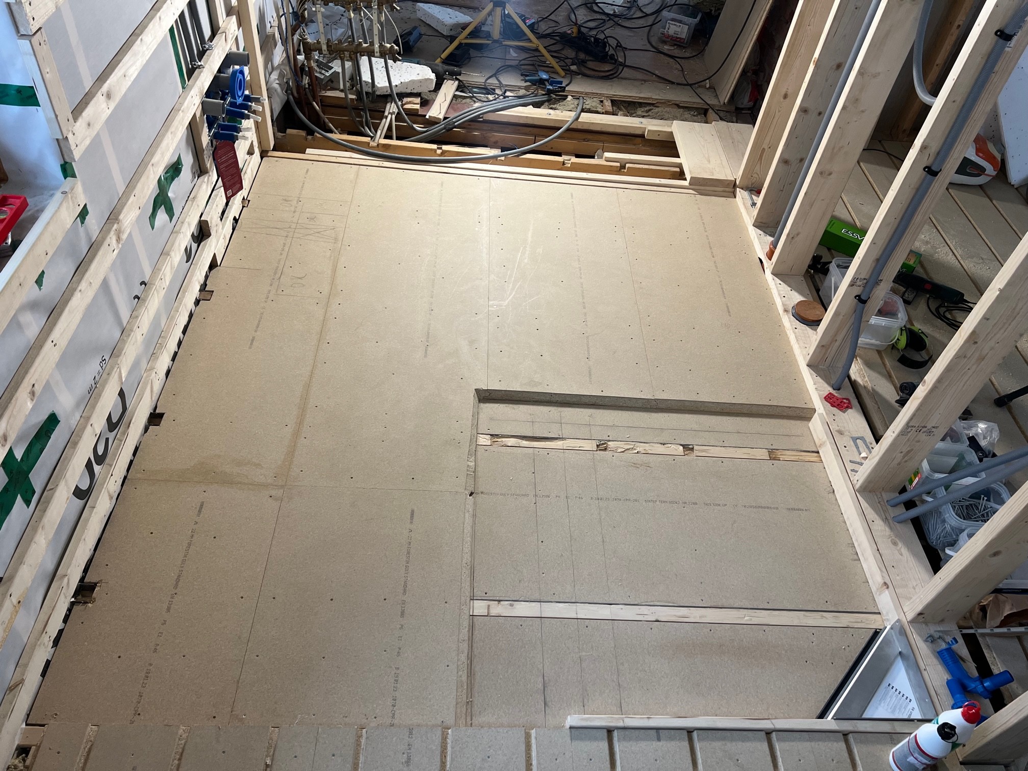
I thought I could show how it turned out, as I myself appreciate threads with a bit of closure.
I made a steel plate reinforcement of the studs, with a low section where the boards are between the studs and a high section where they are on top.
The studs in the low section consist of the old milled-out 170 stud, which was planed down to 145 and received a 145mm high 2mm steel plate on each side. Outside the plates, there is a 120 stud to lay the boards on. PU glue in each layer and through M8 bolts that pull together the entire package.
You could say that these studs, despite their total height of 145mm and 2.7m span, became... Stiff.. I can jump on them and the laser standing next to it barely moves.
A little further away outside the local slope around the well, I have placed the boards on top of the planed-down studs instead of between, and also overlap-glued them so there is 2x22mm chipboard over large parts of the floor.
The feeling is that the floor is as hard as concrete, especially where there are double layers of chipboard.
Finished, the highest chipboard inside the bathroom is about 35mm below the adjacent floor chipboard, and I will thereby achieve my goal of having the finished floor at the same height at the thresholds both inside and outside the bathroom.
Has it been a lot of work? Yes! Would I do it the same way again? Yes!
I made a steel plate reinforcement of the studs, with a low section where the boards are between the studs and a high section where they are on top.
The studs in the low section consist of the old milled-out 170 stud, which was planed down to 145 and received a 145mm high 2mm steel plate on each side. Outside the plates, there is a 120 stud to lay the boards on. PU glue in each layer and through M8 bolts that pull together the entire package.
You could say that these studs, despite their total height of 145mm and 2.7m span, became... Stiff..
I can jump on them and the laser standing next to it barely moves.A little further away outside the local slope around the well, I have placed the boards on top of the planed-down studs instead of between, and also overlap-glued them so there is 2x22mm chipboard over large parts of the floor.
The feeling is that the floor is as hard as concrete, especially where there are double layers of chipboard.
Finished, the highest chipboard inside the bathroom is about 35mm below the adjacent floor chipboard, and I will thereby achieve my goal of having the finished floor at the same height at the thresholds both inside and outside the bathroom.
Has it been a lot of work? Yes! Would I do it the same way again? Yes!


Hi, old thread but how has this worked out for you with the floor, any give?D David_Berglund said:Thought I could show how it turned out, as I myself appreciate threads with a bit of closure.
I made a steel plate reinforcement of the joists, as well as a low section where the boards lie between the joists and a high section where they lie on top.
The joists in the low section consist of the old notched 170 joist that was planed down to 145 and got a 145mm high 2mm steel plate on each side. Outside the plates sits a 120 joist to lay the boards on. PU glue in each layer and through M8 bolts that pull the whole package together.
You could say that these joists, despite their total height of 145mm and 2.7m span became... Stiff..
A bit further outside the local gradient around the well, I've placed the boards on top of the planed-down joists instead of between, and have also overlap-glued them so that over large sections of the floor it's 2x22mm chipboard.
The feeling is that the floor is hard as concrete, especially where there are double layers of chipboard.
Finished, the highest chipboard inside the bathroom sits about 35mm below the adjacent floor chipboard, so I will achieve my goal of having the finished floor at the thresholds at the same height inside and outside the bathroom.
Has it been a lot of work? Yes! Would I do it the same way again? Yes!
Now there are tiles on the floor since long ago, but it became/is incredibly stiff. Much stiffer than the new CC300 floor on 250mm light beam.
Felt almost like jumping on a concrete floor.
Then again, it's an unconventional solution that probably doesn't suit everyone, but I would probably do the same again if I faced the same conditions as I suggested last time.
Felt almost like jumping on a concrete floor.
Then again, it's an unconventional solution that probably doesn't suit everyone, but I would probably do the same again if I faced the same conditions as I suggested last time.
Click here to reply
Similar threads
-
Moisture damage in floor joists - how to handle?
Building Materials and Construction Technology -
19th century house with joists on cc 1800
Building Physics -
Fylla igen hål i bjälklag - massa/fog/spackel/flytspackel?
Fyllnadsmassor -
Tryckt virke golvbjälklag - vad göra?
Fritidshus -
Byta ut grundisolering och fyllnad i bjälklaget i 1800-talstorp
Fyllnadsmassor