Hello!
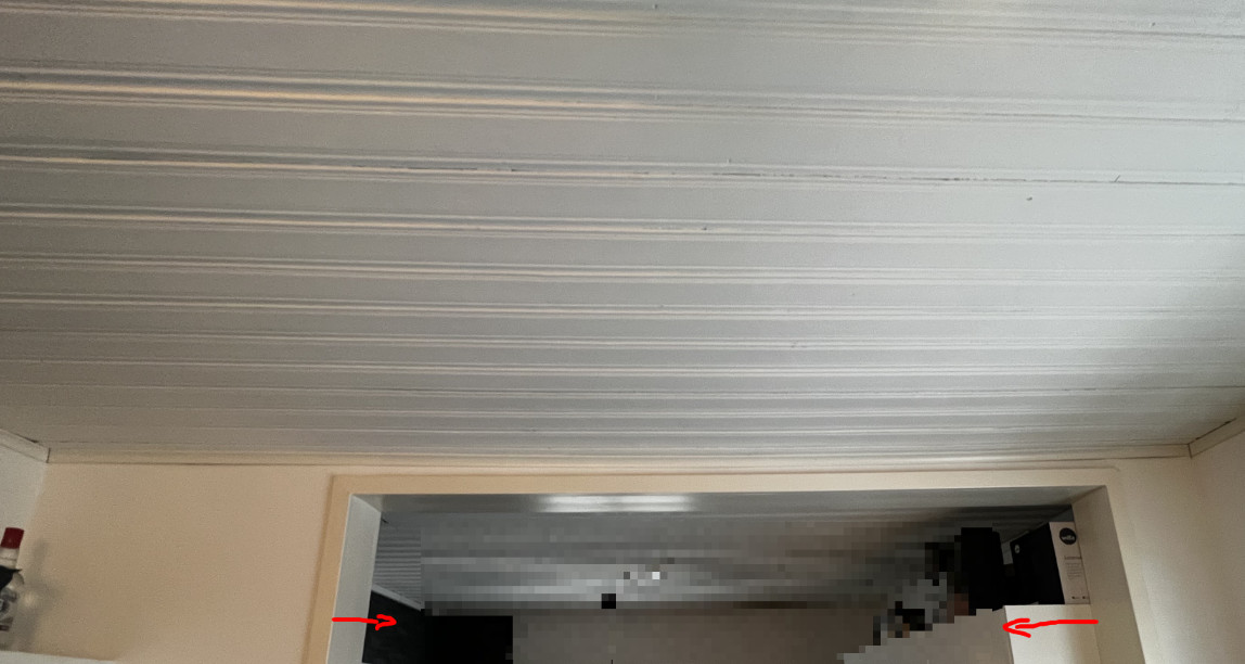
We have a 1940s house we are renovating, and on the ground floor, a wall has been slightly opened up where there was previously a wall and only a doorway between a kitchen and a dining area. This was done by a previous owner.
The beams on the upper floor are joined over the lintel (which was previously a wall) and nailed together with brutally large nails. (Original from the 1940s) We are currently renovating the room on the upper floor and also looked at the lintel that was made. 3 out of 5 studs rest over the lintel, and as I can see, it's first a 50x50 stud that the beams themselves rest on. This looks original from the 1940s. The previous wall likely connected to this stud, but now there is an additional stud under it which is the lintel. That stud looks newer.
If I measure the lintel down to the ceiling below and then the drop on the ground floor, I manage to find that the total lintel seems to be 230mm. So the new "stud" under the 50x50 stud seems to be about 180mm, but together they are about 230mm. The lintel is about 2.28 meters.
The beams on the upper floor, as mentioned, are joined over the lintel, with the beams on one side being 2.85 meters and on the other side of the lintel 3.14 meters. The beams are 230x80mm.
I just wanted to hear from you if this lintel is okay or if it might actually be too weak? Something to address now before applying new screwed and glued floorboards on the upper floor in that case...
The 50x50 rule is a type of wall plate that has always been placed on top of the upright planks, which used to form the load-bearing wall before. As a support beam, you can only count on 50x180 mm, since the 50x50 rule is not glued together with the support beam. 50x180 with a span of 2.3 meters can handle a load of about 400 kg/meter. What load you have depends mainly on the width of the house. If the width is 8 meters, the load on the support should be about 1200 kg/meter. It seems a bit under-dimensioned, therefore. I would think that a switch to a glued laminated beam, 90x225, would fix it, but as mentioned, real data is best.
80x230 (probably 3x9 inches) should work well with the spans you indicate.
The 50x50 rule is a type of wall plate that has always been placed on top of the standing planks, which used to form the load-bearing wall. As a support beam, you can only count on 50x180 mm, since the 50x50 rule is not glued together with the support beam. A 50x180 span of 2.3 meters can handle a load of about 400 kg/meter. Your load depends primarily on the width of the house. If the width is 8 meters, the load on the support should be around 1200 kg/meter. So, it seems a bit undersized. I would think switching to a glulam beam, 90x225, might fix it, but as mentioned, accurate data is best.
80x230 (probably 3x9 inches) should work well with the spans you indicate.
Thanks for the detailed response!
The entire width of the house is 9 meters, but the beams do not go through the entire house because there is another load-bearing wall that the beams rest on at the other end. (Behind that wall, there are stairs. So the full length of the beams (spliced) is thus just under 6 meters. Or is there something else that makes the load based on the entire width of the house?
Suspect that it might be a bit tricky to replace a load-bearing structure since there is also a subfloor before reaching the studs. I can imagine that it would be a bit difficult to prop up beside it in that case because there are smaller studs beside the larger studs, which would be the ones to prop up...
Would it help to build up a bit of wall on both (or one) side/sides of the load-bearing structure to relieve it?
See image below.
I believe the load-bearing structure has probably been there for a long time, and we haven't really noticed that there would be anything wrong actually. Not more wobbling than in any other room, so to speak... But wanted to bring it up now that we have the floor open on the upper floor...
With two heart walls, the load per wall becomes slightly lower, but probably still too large for the transfer beam that is there now. The best option is a floor plan if one wants to calculate with greater precision.
One should take the opportunity when it is open. There are other ways to reinforce. What is best depends on what is accessible. Screwing and gluing plywood from the sides into the hammer beam + the offset is one option. Take a photo from above where the beam can be seen.
You should take the opportunity when it is open. There are other ways to reinforce. What is best depends on what you can reach. To screw-glue plywood from the sides in the hammarband + avväxlingen is one option. Take a photo from above where you can see the beam.
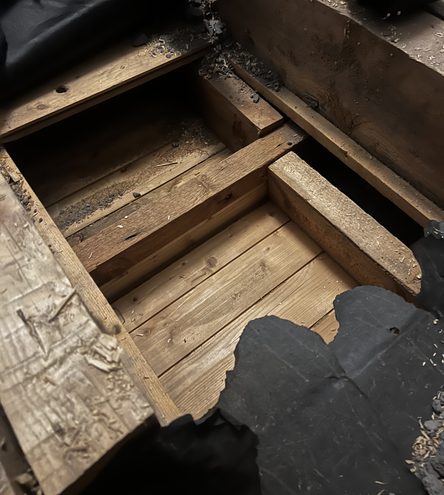
Here come pictures from above. The first picture is a close-up of the avväxlingen that you can probably identify, or yes, the hammarband, and then you can glimpse the avväxlingen underneath. It goes down a bit under the roof too, as you've seen in an earlier picture from the room downstairs.
Blindbotten removed to see the ceiling from the downstairs and the avväxlingen.
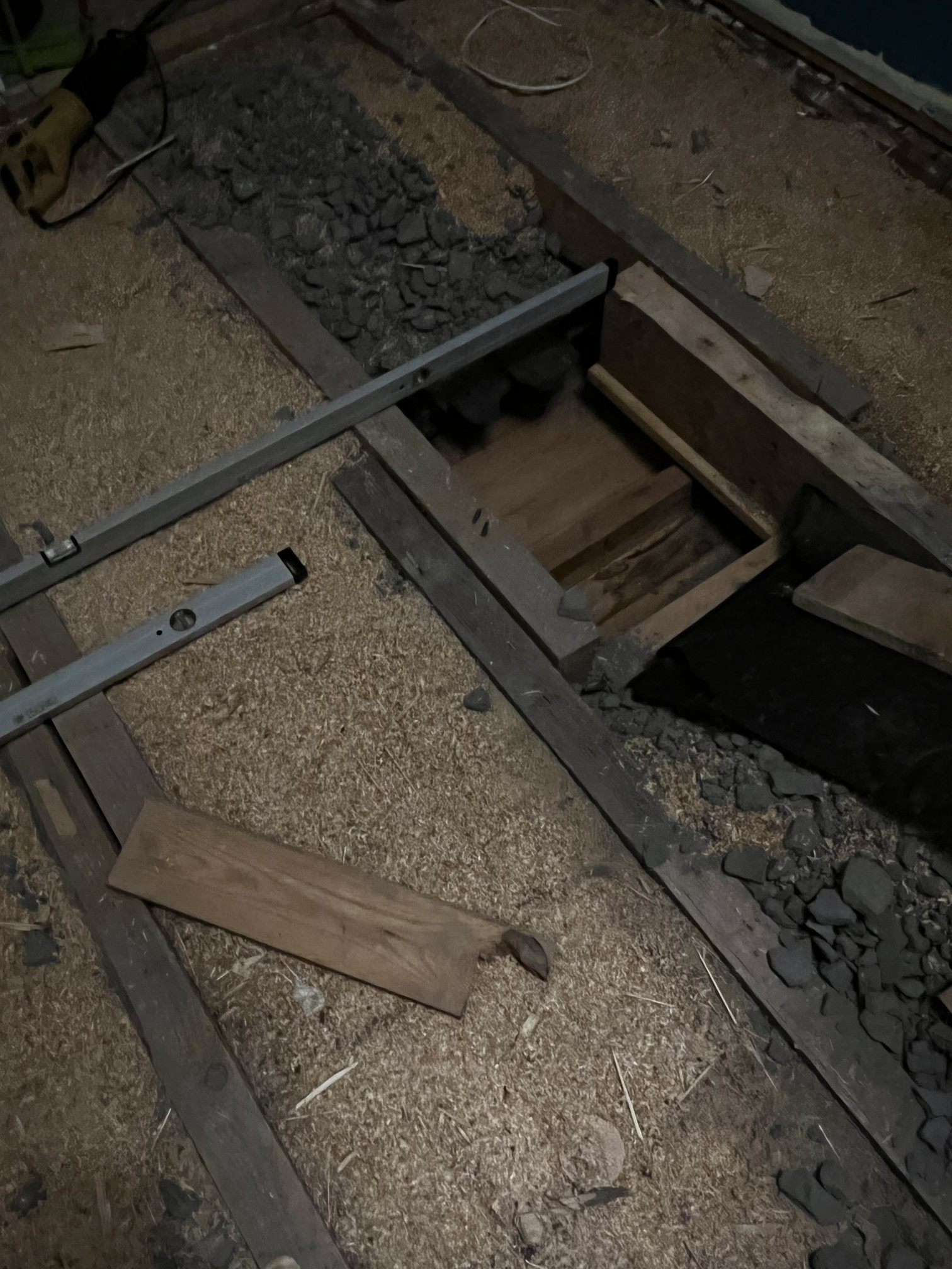
3 studs lie over the existing wall that remains (against each wall and against the wall where the spirit levels are in the above image). 2 studs are almost exactly at the beginning of the avväxling, and you could say 1 stud is in the middle of the avväxling.
Doubtful, unfortunately, depends on whether it's okay to place a piece both above the ceiling and below (i.e., spliced in height). Otherwise, I would have to tear away part of the kitchen ceiling, and it's first the original ceiling and then beadboard planks under the original ceiling. Is it plywood that's glued to the beam, I assume?
How much extra strength does gluing on plywood provide? Does it become much stronger? It might be worth trying to access it in that case. What thickness is needed then?
I was also thinking of placing some angle brackets at the joints. Maybe it doesn't make much difference. Possibly add some extra screws through the beams so the nails that are there now get some help.
What gives the most is if you can make the hammarband (50x50 rule) work in conjunction with the avväxlingsbalk (50x180 rule) through the screw-glued plywood. 12 mm k-plywood is sufficient. The thicker and higher quality, the better. If a 50x180 beam can handle 400 kg/m, then a 50x230 can handle more than double.
What gives the most is if you can get the hammarband (50x50 rule) to collaborate with the avväxlingsbalk (50x180 rule) through the screwed plywood. 12 mm construction plywood is sufficient. The thicker and higher quality, the better. If a 50x180 beam can handle 400 kg/m, then 50x230 can handle more than double.
Ok, can you screw and glue in each compartment or must it be together over the whole avväxlingsregeln? The problem that arises in such a case is that the studs supporting the roof are attached to the hammarband... So you can't get a 2.3-meter plywood piece against the rule without it being maybe a 60 cm plywood piece and then another 60 cm or whatever it is between the studs...
And then I have to dig out the avväxling in this mess that's in the floor structure
It seems to be slag stone and wood shavings.
* If using small filler pieces doesn't work, could it be an idea to reduce the avväxling?
If I were to put up some studs and support the avväxling in the kitchen, that would be doable too.
Could reduce the avväxling by about 50 cm...
* I could put an additional avväxling below the avväxling and screw and glue plywood between these two. Could that work? The ceiling is high enough that putting an extra rule below the rule would work. Though, it would only be screwed and glued to the lower part of the avväxling in that case..
If it were possible to put another rule below the avväxling, what dimensions should it be in that case? (It might not be able to build too much...)
If you can shorten the span by 50 cm, that should be sufficient. Otherwise, it's best to use long plywood pieces.
Sounds good, then it will be a small project in the kitchen.
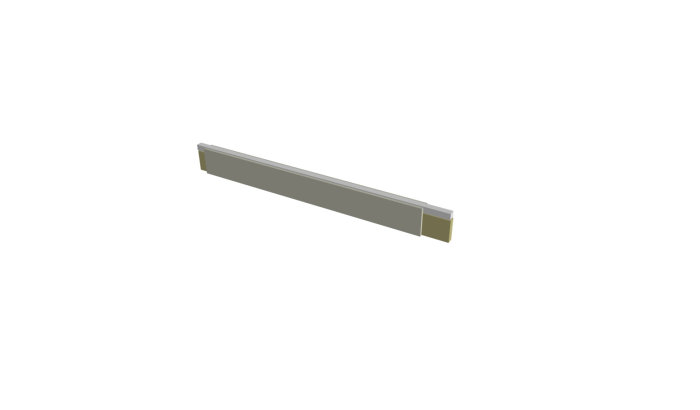
If I don't shorten the span, would it work to put a reinforcement below the existing beam and glue and screw plywood between the existing and new beams? Because that almost seems the easiest to do and impacts the kitchen the least. Just like you glue and screw plywood between the beam and the top plate, you should be able to do it in reverse too, right, meaning from below?
In that case, what dimensions should the new beam be?
I have a prop so I can push the beam up against the existing beam and glue plywood between the beams if needed.
If I don't shorten the span, would it work to place a reinforcement below the current one and glue-screw plywood between the existing reinforcement and the new one? It feels almost the easiest to do and affects the kitchen the least. Just as you glue-screw plywood between the reinforcement and the rafter, you should be able to do it the other way too, right, like from below?
In that case, what should be the dimensions of the new beam?
Absolutely. It is primarily the height of the reinforcement that matters.
Vi vill skicka notiser för ämnen du bevakar och händelser som berör dig.