5,200 views ·
15 replies
5k views
15 replies
Level floor joists for chipboard bump against exterior walls
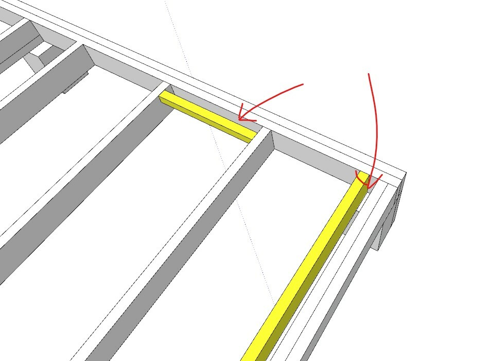
Drawing on a floor structure that will have 22 mm floor chipboard on it.
How do you usually do it at the yellow markings on the outer edges? Where the beams are covered by outer and inner walls, which means the chipboard doesn't get any support.
Do you put noggins in the same dimension as the beams to support the chipboard, or how do you do it?
How do you usually do it at the yellow markings on the outer edges? Where the beams are covered by outer and inner walls, which means the chipboard doesn't get any support.
Do you put noggins in the same dimension as the beams to support the chipboard, or how do you do it?

You have an additional joist on the inside of the wall, then you install noggings between the joists where the wall crosses the joists with a 45x45 as support for the floor chipboard.H Haz6909 said:Drawing on a floor structure that will have 22 mm floor chipboard on it.
How do you usually handle the areas at the yellow markings on the outer edges? Where the joists are covered by outer and inner walls, meaning the floor chipboard does not get any support.
Do you install noggings in the same dimension as the joists to support the floor chipboard, or how do you do it?

You can place 45x70 in between and insulate the gap before you mount the other beam...45+70=115mm, then you have 40mm left to screw the floor chipboard into...H Haz6909 said:
If you want more, you'll simply have to take something wider...
Last edited by a moderator:
Ok, do you have double outer frames?H Haz6909 said:
Because if you have double frames, then 45x45 is enough...
Only at the right arrow, you can have either 600 c/c or 1200 c/c on the blocks so that the insulation fits between them...
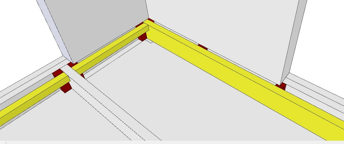
Yes, the outer frame is 2 * 145 all around. I drew a new sketch where the standing 45x45 (red in the picture) with 60 cc (in the gap between the outer frame and the extra beam).
Shouldn't the long side of the floor chipboard against the outer wall on the left also have a support rule underneath, with the same principle, standing 45x45 (red in the picture) between the outer frame and the noggings?
Shouldn't the long side of the floor chipboard against the outer wall on the left also have a support rule underneath, with the same principle, standing 45x45 (red in the picture) between the outer frame and the noggings?
On the long side, the 45x45 only has the task of taking up the deflection of the chipboard floor so that it doesn't flex between the beams, so it's not needed if you screw glue the chipboard floor.H Haz6909 said:Yes, the outer frame is 2 * 145 all around.
I drew a new sketch where the standing 45x45 (red in the picture) with 60 cc (in the gap between the outer frame and the extra beam).
Shouldn't the long side of the floor chipboard against the outer wall to the left also have a support rule underneath, with the same principle, standing 45x45 (red in the picture) between the outer frame and the noggings?
At the end, however, the first beam is part of the load-bearing floor construction that is meant to take up the actual weight that the floor is subjected to.