This is my first post on Byggahus.se, hope I'm posting in the right forum.
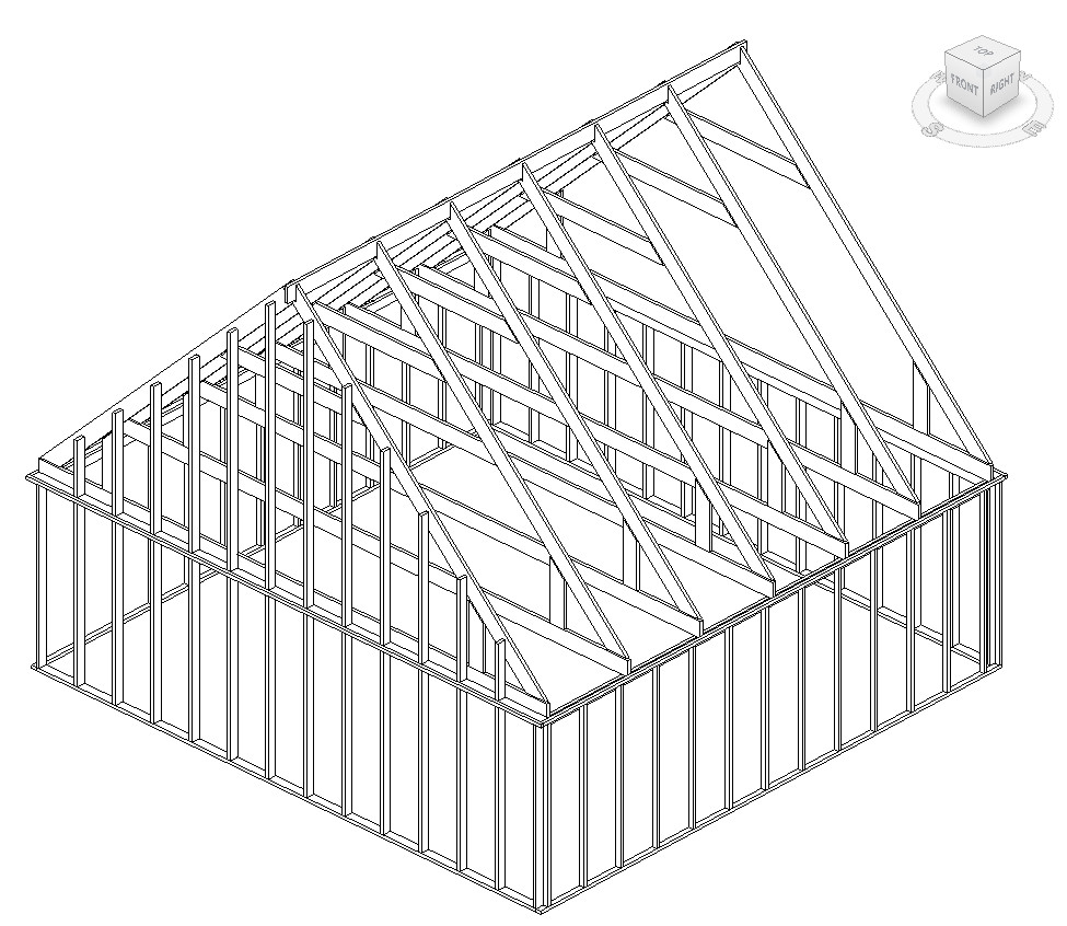
We are planning a larger extension project for our single-story year-round vacation home of 60 sqm BYA with a loft where we want to both extend about 40 sqm BYA + raise the roof from 27° (loft) to 45° (1.5 stories) + an Attefall addition for the entrance, to make it a larger permanent residence.
We are limited by the zoning plan to 100 sqm BYA and a building height of 3.0m (hopefully a small deviation on the building height will be allowed to achieve a good upper floor and mezzanine).
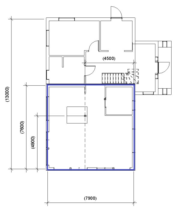
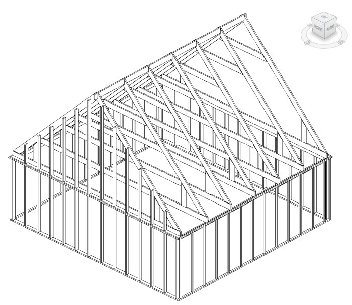
We have developed a floor plan that we are starting to like now, but we have a problem with wanting an open floor plan on the ground floor for the kitchen/living room and we get long spans for our potential roof trusses of about 7.9m.
Due to the max building height of 3.0m, we want the mezzanine as low as possible.
We would preferably not have any columns either, but if we have to, it would be best by the kitchen island.
What I wonder is if anyone has any ideas on how to technically solve this before I start contacting truss suppliers, constructors, etc.?
I have tried doing some calculations on the mezzanine and it looks bleak with a completely open floor plan..
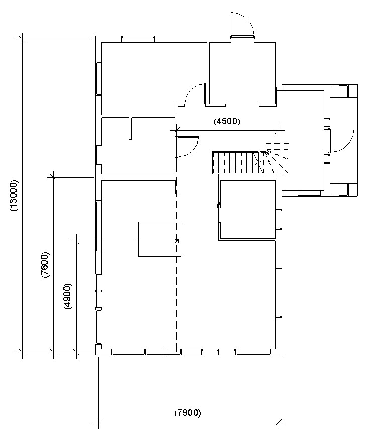
However, if I go with a mid-support by the kitchen island (4.5m from the right wall), it seems possible with 2x45x220 C24 or 90x225 GL30h cc 600, but it feels like an insane amount of timber (cost) and does a HEA beam work as a mid-support, for example? and is a pillar required in such a case at the intended position? (I have little knowledge of what I need to consider in the calculations for that type of beam and setup)
For the extension, we will be able to use load-bearing interior walls, so I don't see the need to do anything special there, ordinary framework trusses cc 1200 and mezzanine beams should work fine.
More info:
Snow zone 3.0 kN/m²
Intended metal roof
Existing building: Single-story year-round vacation home with loft on a concrete slab (built in 2001) with 45x70mm cc 600 load-bearing exterior wall frame (Will this be a problem as it's only a 45x70mm stud?)
Intended to add insulation to the exterior walls, replace some windows and exterior cladding on the existing building during the renovation, so minor alteration of the exterior wall is possible if needed, but it feels a bit much to replace the frame...
About the drawings:
Blue walls are the existing building
Dashed line is a potential beam I have drawn in (HEA to keep the building height down?)
X-square by the kitchen island is a potential position for the mid-pillar for the beam.
Am I missing anything else? Will point loads on the slab also limit?
Does an HEA beam work as a central support, for example? And is a pillar needed in such cases at the intended position? (I'm not well-versed in what needs to be considered in the calculations for this type of beam and setup)
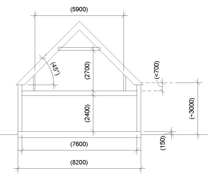
To begin with, I don't really understand your sectional sketch. Don't your trusses extend over the span of 7.6m? You mention that they are supposed to extend over 7.9m.
Do you mean that you intend to use an HEA beam as a pillar support? Or that your intermediate floors will consist of HEA beams? Either way, it's a long span without a pillar. When it comes to the pillar, you need to check, among other things:
Compressive strength with respect to buckling
Bending strength
Possible compression and bending interaction
The concentrated load can affect the slab, for example, through punching.
First of all, I don't quite understand your section sketch. Don't your trusses span 7.6m? You mention they should span 7.9m.
Do you mean to use HEA beams as a column support? Or that your intermediate floors will consist of HEA beams? Regardless, it's a long span without a column. When it comes to the column, among other things, you need to check:
The compressive strength with respect to buckling
The bending strength
Possible compression and bending interaction
The concentrated load can affect the plate, for example, punching might occur.
Hi,
Thanks for your response!
7.6m is the internal measurement of the outer walls, and the distance between the joists that the trusses rest on is about 7.9m.
I mean that I would like to use an HEA beam as the center support for the intermediate floor. Preferably at the level of the intermediate floor so that it doesn't add much to the height.
I have the ability to do the calculations myself, but I am uncertain about which loads I need to account for, as well as the criteria that apply to the affected parts (HEA support, columns, and plate).
Do you have any input on this?
Hi,
Thanks for the response!
7.6m is the inner measurement of the outer walls and the distance between the studs that the trusses rest on is about 7.9m.
I mean that I would like to use an HEA beam as the central support for the intermediate floor. Preferably at the level of the intermediate floor so that it doesn't add extra height.
I have the ability to do calculations on this myself, but I'm unsure what loads I need to include, as well as what criteria apply to the relevant parts (HEA support, pillar, and slab).
Do you have any input on this?
For the intermediate floors, you have a useful load from the loft, then you need to check the compressive strength perpendicular to the fibers at the supports.
For the HEA beam itself, it is loaded by the support forces from the load of the intermediate floors as well as in the form of support moments. The pillar is in turn loaded in a corresponding way, with a compressive force equivalent to the support force and support moment from the HEA beam. Note; Don't forget the self-weight of all the affected parts.
The criteria you mention are numerous and it's too much to go through here. There are quite a few checks and equations you need to use. I assume when you perform the calculations you use some FEM program? or some CAD program with some built-in program that solves the system for you?
For the intermediate floors, you have a useful load from the loft, then you need to check the compressive strength perpendicular to the fibers at the supports.
For the HEA beam itself, it is loaded by the support forces from the load of the intermediate floors and in the form of support moments. The column is, in turn, loaded in a corresponding way, with a compressive force equivalent to the support force and support moment from the HEA beam. Note; Don't forget the self-weight for all the concerned parts.
The criteria you mention are numerous, and it's too much to go through here. There are quite a few checks and equations you need to use. I assume that when you perform the calculations, you use some FEM program? or some CAD program with a built-in program that solves the system for you?
Yes, I work with FEM daily and have a few different tools that I can use. I have tested Finnwoods, though it lacks HEA beams in that tool, but I think it has good support for construction standards.
I feel that I have relatively good control over how the forces act in the construction. What is unclear to me is the magnitude of the forces that I should include in the calculations based on typical construction standards, as well as their criteria. So it's a bit unfortunate that it can't be discussed here in the thread... Do you know where I can access them, or if you (or someone else) have the opportunity to calculate this? Is there anything missing to be able to perform the necessary calculation?
This absolutely does not require any FEM tools. Elementary cases for beams and EKS11 as support are quite sufficient. There are also good handbooks on Swedish wood.
You absolutely don't need any FEM tools for this. It's quite sufficient with elementary cases for beams and EKS11 for support. There are also good handbooks at
Bbossespecial said:
You absolutely don't need any FEM tools for this. It's quite sufficient with elementary cases for beams and EKS11 for support. There are also good handbooks at svenskt trä.
svenskt trä.
I agree with you that one shouldn't need to run FEM for this.
Thanks for the guidance on EKS11 and Svensk trä's handbooks. I'll take a look at them.
However, if you or someone else already has something ready based on EKS11 that can calculate this with experience, you are welcome to do so while I try to get into the handbooks
A good start could be to check that the placement of the pillar is not such that there is lifting in the outer pillar in the shorter compartment.
As I mentioned earlier, I am primarily interested in seeing if I can manage without a pillar. But absolutely, we should check that if it turns out a pillar is necessary.
It is a long beam and there is always a risk of disturbing vibrations when people move upstairs. You could use your FEM tools and calculate a bit on vibrations. Alternatively, increase the size of the beam and live with any vibrations. It might be that the function upstairs isn't so sensitive to a bit of vibration?
It is a long beam, and there is always a risk of disturbing vibrations when people move upstairs. You could use your FEM tools and calculate the vibrations a bit. Alternatively, you could increase the beam dimension and live with potential vibrations. Perhaps, the function upstairs is not so sensitive to a little vibration?
Interesting aspect in the whole thing. I'll definitely have to simulate that later then Regarding function, most of it will be above a bedroom, so the sway there versus completely open in the kitchen/living room is lower on the priority list. (To a certain extent, of course)
Vi vill skicka notiser för ämnen du bevakar och händelser som berör dig.
")


MarcusL89 said:
Hi,