Hello!
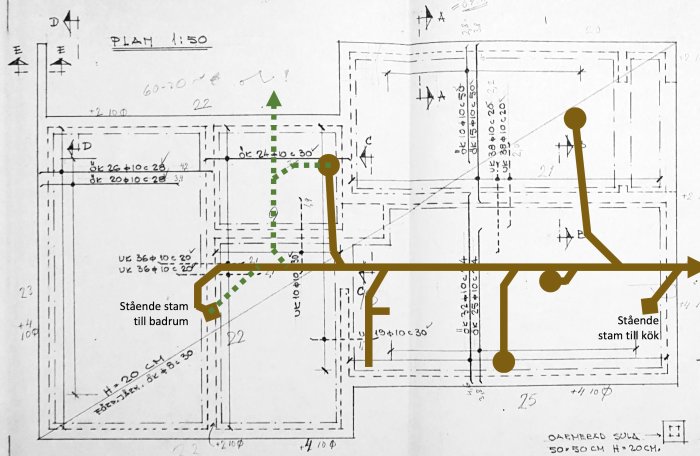
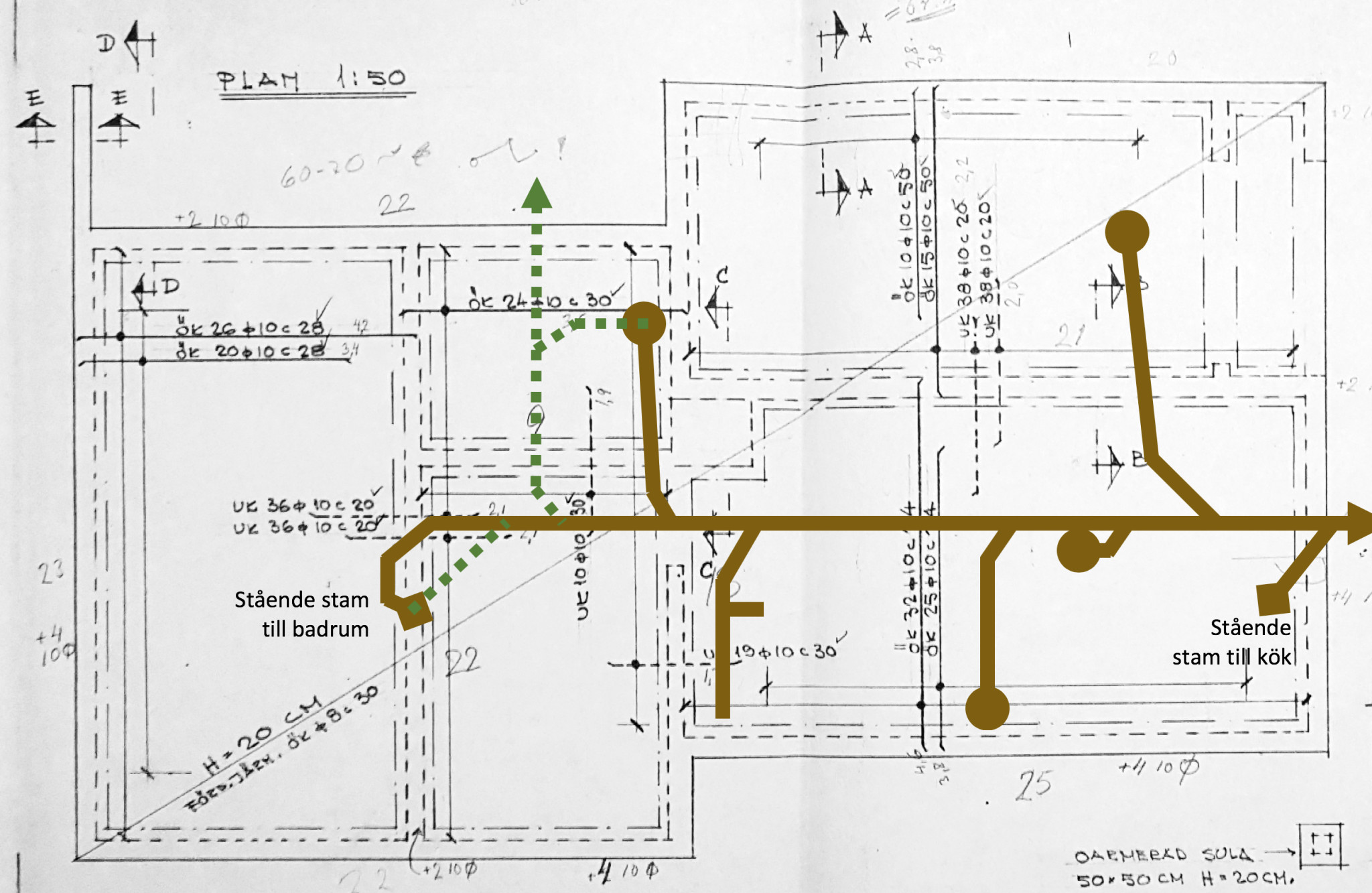
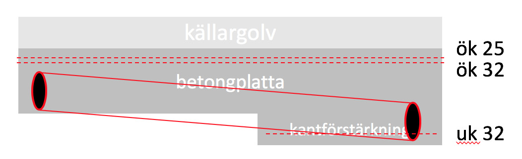
I am considering cutting/chiseling and replacing the cast iron sewer pipes that are in the basement floor, but I am unsure how to handle the reinforcement of the bottom slab. The sewer pipes and reinforcement are arranged as follows:
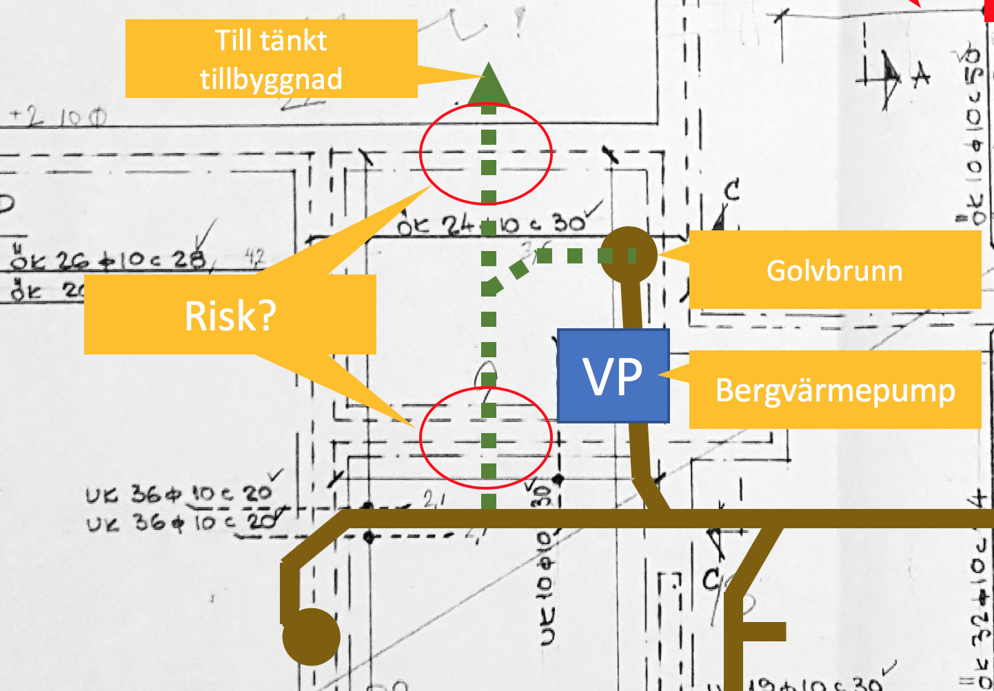
The dashed green line is a bit of rerouting I was planning to do.
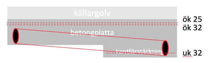
On the reinforced bottom slab, I suspect there is about a 10cm poured concrete floor.
Based on how deep the sewer stack is at the outgoing cleanout and the length of the stack, I assume the sewer pipes are between the lower edge reinforcement and the upper edge reinforcement.
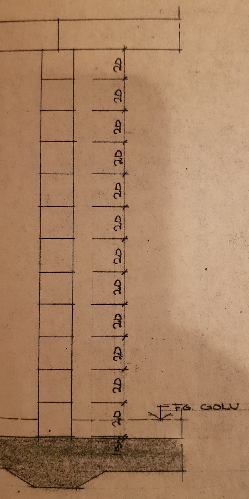
I want to start by saying that it's not fi25 or 32-bars, but rather the number being referred to. The dimensions are as you see, 8 or 10, except for reinforcement in the beams where you have longitudinal 16mm.
In the rooms, there is no danger. Reinforcement is not really needed there and is probably only placed with additional support as crack reinforcement. The critical part is under the inner wall and when you go out through the outer wall. It's difficult to answer without knowing exactly how you plan to run your new work, given that you already have 100mm(?) cast on the floor.
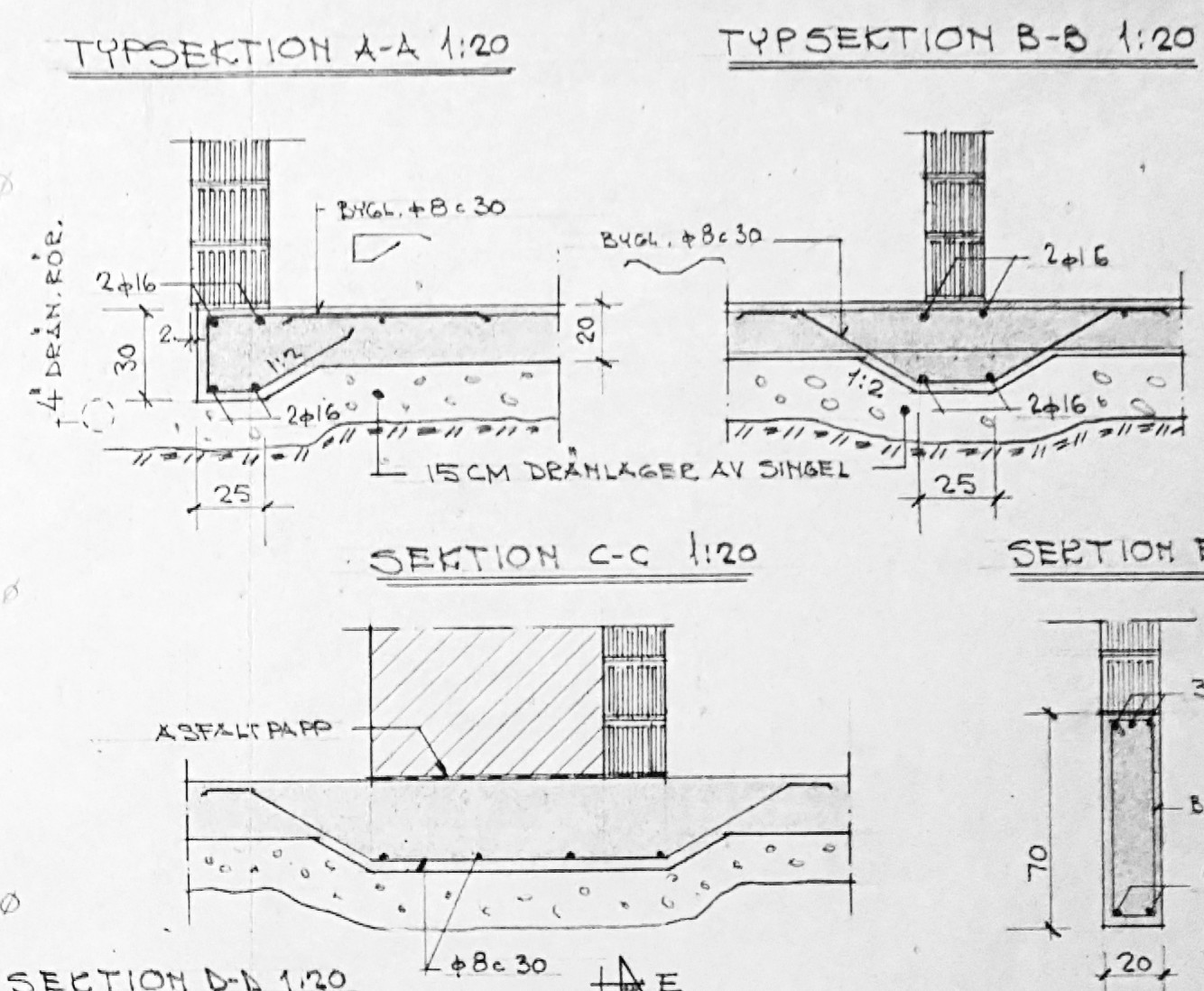
I become a bit questioning when I see the reinforcement plan and when the slab is so thick. The slab seems to be reinforced for a force from below. The drainage pipes can be seen in a detail so it's not water pressure. Is the house on clay?
I want to start by saying that these are not fi25 or 32 bars, but instead it's referring to the number. The dimensions, as you can see, are 8 or 10, with the exception of reinforcement in the beams where you have longitudinal 16mm.
Aaaah, I interpreted "ÖK 32" and "UK 38" as how many millimeters the bars were from the top and bottom edge, respectively, but it's actually the number.
Do I need to measure on the sectional drawings to figure out how deep the reinforcement bars are, or how do I find this out?
CC.Lundin said:
There's no danger in the rooms. ÖK is not really needed there and is probably laid only with suspenders as crack reinforcement.
That's good to hear that they didn't serve any load-bearing function.
CC.Lundin said:
The critical part is under the inner wall and when you go out through the outer wall.
It's hard to answer without knowing exactly how you plan to route your new one, given that you already have a 100mm(?) casting on the floor.
When going out through the outer wall, I thought I'd let the existing cast iron pipe remain (until I eventually decide to replace the concrete pipes underground out to the street).
Do you mean there could be problems with this routing?
This is meant to be a branch to an extension and to the existing floor drain. The reason I intend to run a new branch is because the existing one goes under the geothermal heat pump.
I'm a bit puzzled when I see the reinforcement plan and the slab is so thick. The slab looks like it's reinforced for a force from below. The drainage pipes can be seen in a detail so it's not water pressure. Is the house on clay?
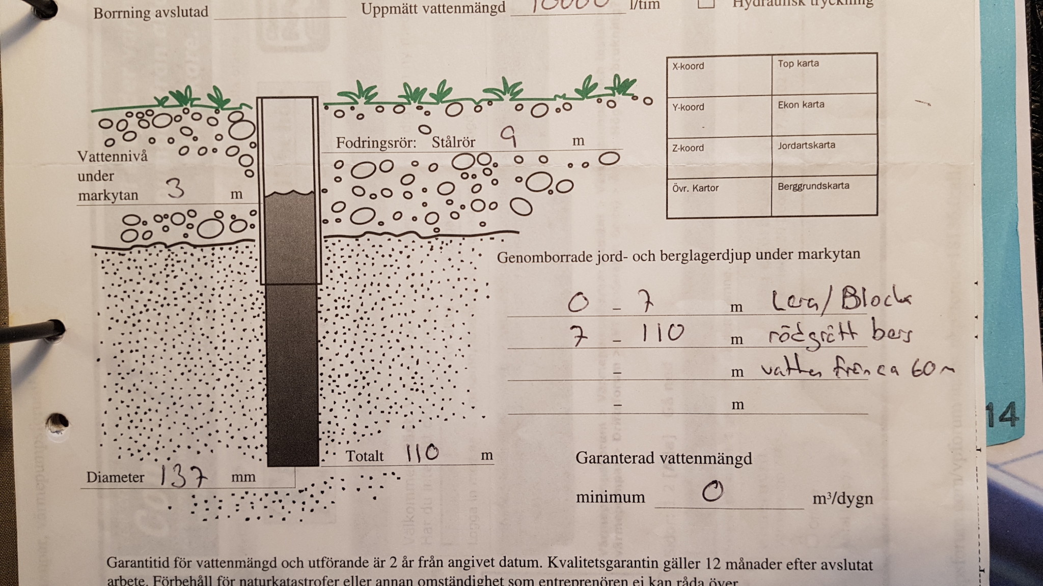
Yes, it's clay and blocks down to 7m depth according to the protocol from the geothermal drilling.
I interpret it as the groundwater is 3 m below the surface. Could that be possible?
The area we live in is an old lake bed.
Do you mean that the house is designed like a flat-bottomed boat that "floats" on clay and that one would weaken the bottom of the "boat" if the top reinforcement, which goes between the walls, was cut?
Yes, it's clay and blocks down to a depth of 7m according to the protocol from the geothermal drilling. I interpret it as the groundwater is 3 m below the surface. Could that be right?
[image]
The area we live in is an old lakebed.
Do you mean that the house is designed like a flat-bottomed boat that "floats" on clay and that you would weaken the bottom of the "boat" if you cut the top edge reinforcement that runs between the walls?
Yes, exactly, a good analogy The load from the walls wants to compress the clay and "sink". The effect is that the clay between the walls will push upwards on the slab. The slab thus holds against "settling" directly under the walls and distributes the load over the entire slab instead. So it's important to make sure to reinforce the slab again if you cut the top edge bars.
So you need to ensure that the plate is reinforced again if you cut the top bars.
But can it be done without risk, i.e., cutting the top bars to be able to replace the pipes and then "patching them up"?
How would one "patch them up"? Is it enough to just dowel new bars into the concrete on the sides of the trench you've made, or do you have to weld the bars you've cut, or...?
The ground pressure from the clay is essentially 0 in this context. It would have been an issue if the house was situated five meters down with clay around it, but then the problem that the entire house wants to lift would have been a bigger problem.
Of course, concrete always works better with reinforcement and is almost always needed, but here I would absolutely not be worried.
Should you, against all odds, want to splice them together, injecting new material is the way to go, or preferably chip away an additional 50cm on each side of the tracks (actually 100cm if you want to be completely by the book). This is to be able to lay in new rebar, and then cast everything together again. Welding in construction rebar should only be done under very controlled conditions, so that option is off if you still want to accommodate the rebar.
To answer your earlier question, they should lie at a depth of approximately 25mm if correctly laid.
Here, you have ground pressure from the clay. The cellar stands on a spring bed. When the springs are compressed, the load is distributed further. The reason for the thick slab is to be able to distribute the house's loads across the entire slab, thereby achieving an even stress distribution over the clay to avoid uneven settlements.
Reinforcement is necessary and is not unnecessary in this case. There are no problems with chiseling a groove as it involves such a short time. You should follow the splicing as mentioned above unless you bring in a welder with the right competence.
I "laid out" the reinforcement specified in the drawing in a Sketchup model.
I thought it would give a clearer picture of how much reinforcement I have to cut and restore and how the drainpipes are positioned in relation to the reinforcement.
It seems like there's quite a bit of reinforcement that needs to be cut.
The horizontal pipe seems to come in at the lower reinforcement and then stays below the upper reinforcement (assuming a slope of 1cm per meter).
I haven't managed to figure out whether the branches go just under the upper reinforcement or if they lie on top of it (in the roughly 10cm cast floor).
I'm still unsure if it's smartest to run the drainage to the proposed extension through the boiler room or through the garage.
It's really not a small project you are thinking of starting. Just have to ask, is it really necessary?
What problems do you have with the system?
I understand that you are thinking of installing new, but it is much less work to just groove it. It is also possible to run it above the slab, assuming that the new construction is not on the basement level.
I am a bit puzzled when I see the reinforcement plan and when the slab is so thick. The slab seems to be reinforced for a force from below. The drainage pipes can be seen in a detail so it's not water pressure. Is the house on clay?
Do you think 200mm is thick? I would say it's completely normal.
It's certainly no small project you're planning to start. Just have to ask, is it really necessary?
What issues do you have with the system?
Good question! Maybe you shouldn't fix what's working
There were two things that made me consider this. Firstly, I would like to remove the plastic mat in the laundry room and lay tiles instead and also replace the two old cast iron floor drains there. Secondly, I'm considering an extension, with a basement, and need to extend the drainage there. Before I take on these jobs, I want to ensure that the drainage pipes are okay. They're still over 50 years old, and the camera inspection during the last flushing indicated that it might be time to address them.
Rickard.ag said:
I understand you're thinking of installing new ones but it's much less work to just break it open
Now I'm not sure if I follow what you mean. The idea is to break up the existing ones (the red pipes in the picture), insert new pipes, patch the reinforcement, and cast again.
The new routing I'm considering (the yellow pipes in the picture) is to the extension (either via the boiler room or the garage) and the cast iron drain in the boiler room (the existing pipe goes under the geothermal pump) and potentially a shorter stretch to the vertical stack to the bathroom (the existing pipe makes a strange loop before it goes up).
Rickard.ag said:
It's also possible to route above the slab if we assume the new construction is not on the basement level.
My father-in-law has also suggested that we should raise the floor in the basement a bit to be able to route new pipes above the top reinforcement.
Last edited:
Vi vill skicka notiser för ämnen du bevakar och händelser som berör dig.

 The load from the walls wants to compress the clay and "sink". The effect is that the clay between the walls will push upwards on the slab. The slab thus holds against "settling" directly under the walls and distributes the load over the entire slab instead. So it's important to make sure to reinforce the slab again if you cut the top edge bars.
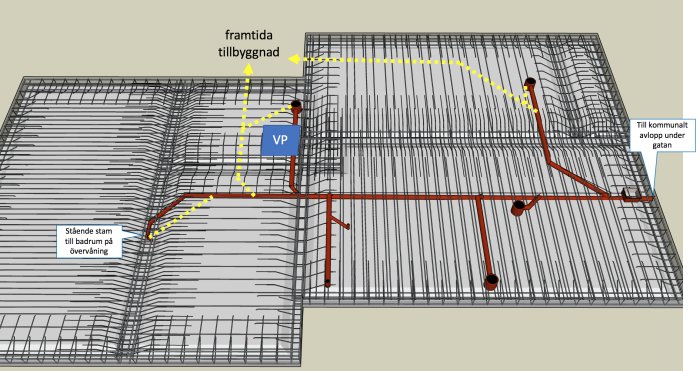


Rickard.ag said: