31,141 views ·
29 replies
31k views
29 replies
Removal of load-bearing wall, installing beam support in the attic?
I have a single-story house with a basement and plan to remove a load-bearing wall. Previous owners had already removed part of a load-bearing wall a long time ago and replaced it with a standing beam above the rafter ties. Currently, 3 bays (2 trusses) have been spanned, and I would like to support an additional 2 bays in this way. Essentially, this beam, which is just over 3.60 meters, would be replaced with a stronger beam that covers a total of 5 bays. Both ends will rest on posts placed above the masonry basement walls.
Is it possible to do it this way? Any opinions?
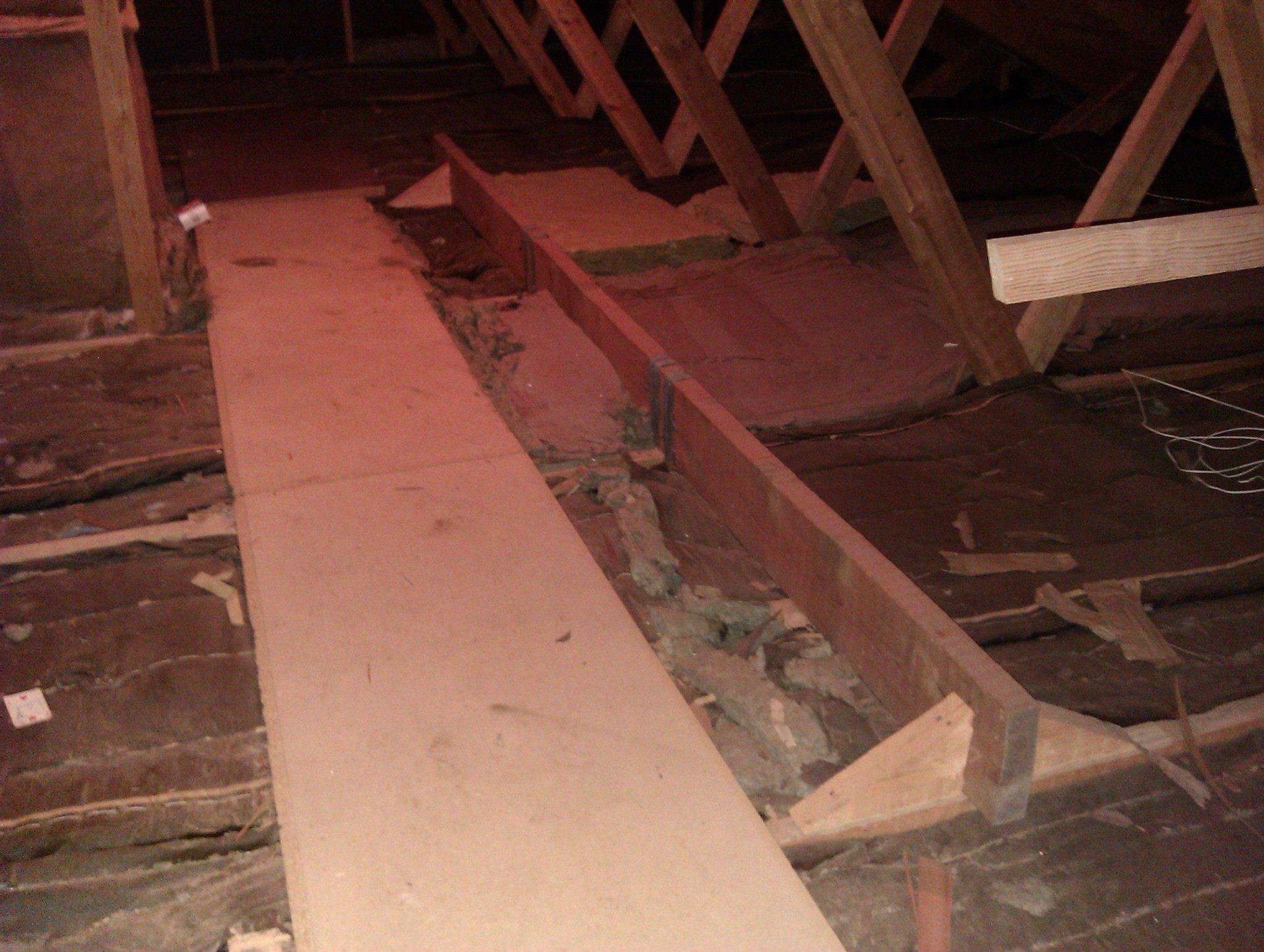
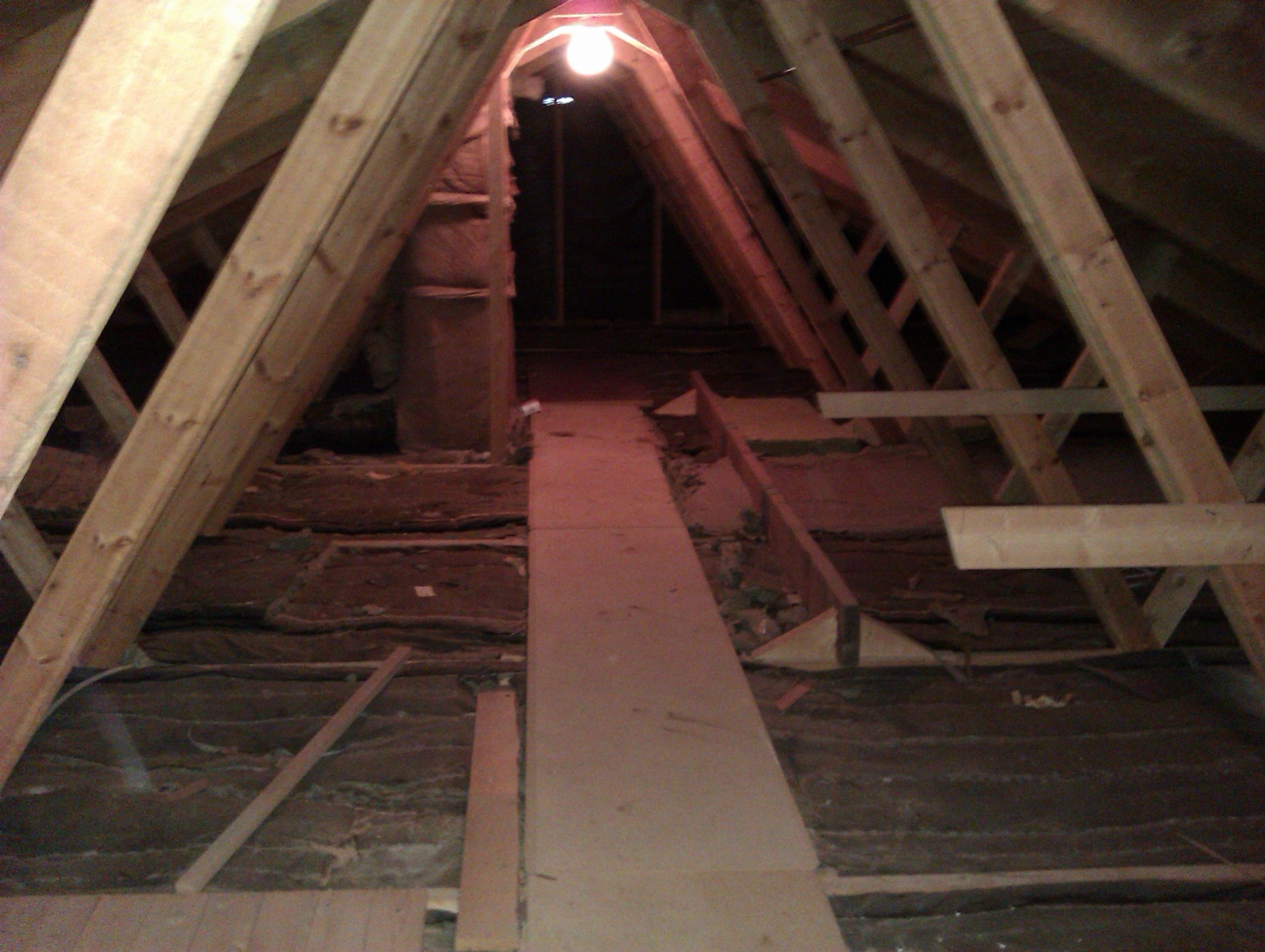
In the pictures, you can see the attic and the current support.
Last edited:
Yes, it can be; it's not certain that the brick walls can handle the load. Check this carefully with an engineer who can calculate the tensile strength. I was at a place where they couldn't handle it; they had to install new piers in the basement to take parts of the load. It became quite a large project, but it went well.jaeger77 said:
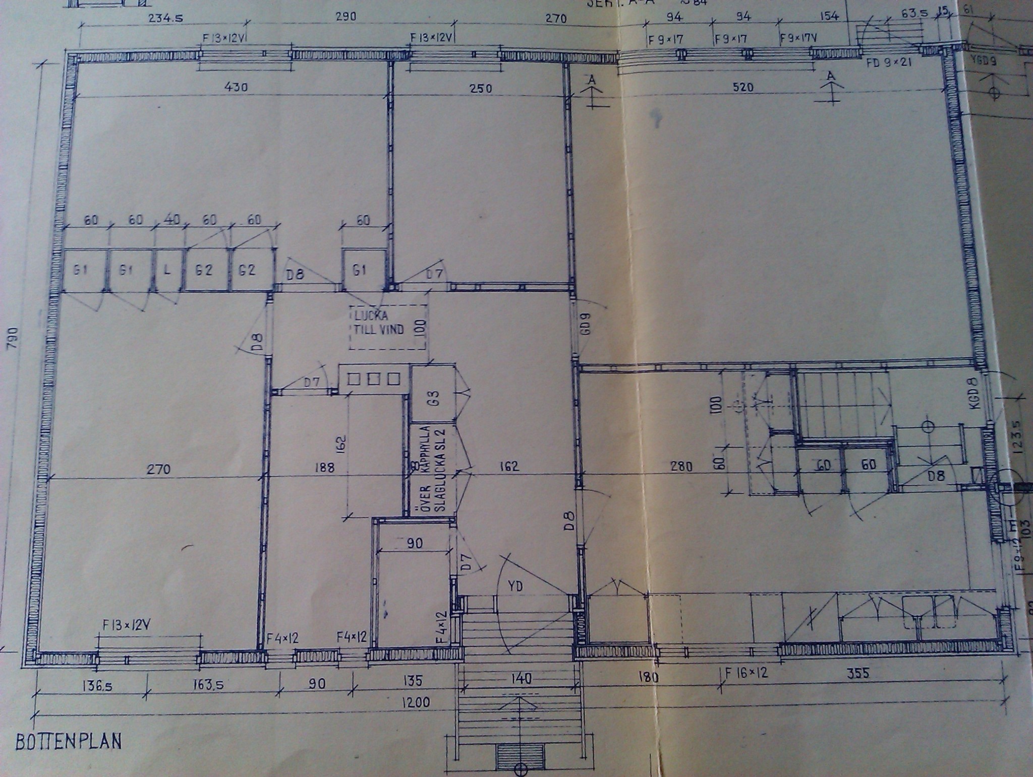
Yes, have blueprints and mtrlspec. The entire basement is built with 20cm concrete hollow blocks. Now that I look at them, I see that part of the load-bearing wall has been removed where there used to be extra posts up to the roof truss. Have to get up into the attic...
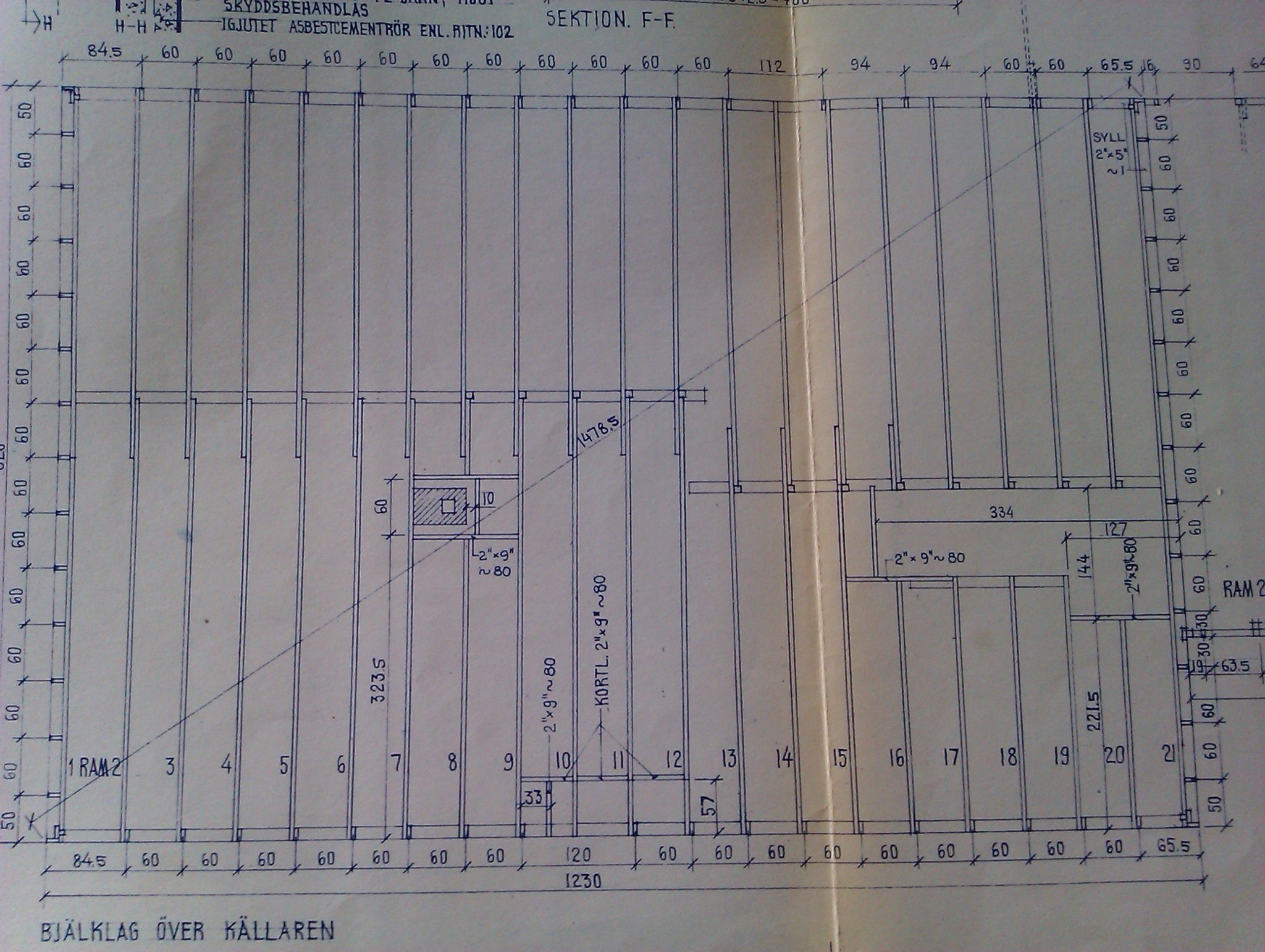
Previously, the load-bearing wall from line 9 to 13 has been removed and replaced according to the image at the top. Now the plan is to remove the other wall from line 12 to 17 and support it in the same way. The beam will span between line 9 and 17. This will result in a total of 5 sections, 4 trusses. The trusses are located on uneven lines. Do I need to hire an expensive consultant for this modification, or should I install an IPE or glulam beam of appropriate dimension?

I should start by pointing out that I am not a civil engineer or have any significant expertise in building construction.
But I think it looks like your roof trusses are of the truss type, and if so, I'm not so convinced that the wall there carries any significant load at all. The trusses are self-supporting (I think).
The beam that is there today seems to be very poorly fastened to the joists it is expected to support. If there were any significant load, the fastenings would be pulled apart.
I take back what I said about inadequate fastening, I didn't see the nail plates.
Thank you for the response hempularen, you have helped me on other occasions if I remember correctly.
Yes, these are probably trusses of the fackverk type, like a W-truss. How does such a truss take up its load? Might there not be such a high load on the hanbjälke?
Yes, these are probably trusses of the fackverk type, like a W-truss. How does such a truss take up its load? Might there not be such a high load on the hanbjälke?
Hello!
If you see how the basement walls are placed directly under the walls you intend to dismantle, it suggests that they are load-bearing.
I would raise the question with a structural engineer.
Because if they are load-bearing, a structural engineer needs to calculate your support beam considering the current snow load zone, etc. It looks like it will be quite long.
Best regards, Torpalainen
If anything happens, you are the one responsible.
Now I have examined the drawings in more detail and come to the following observation:
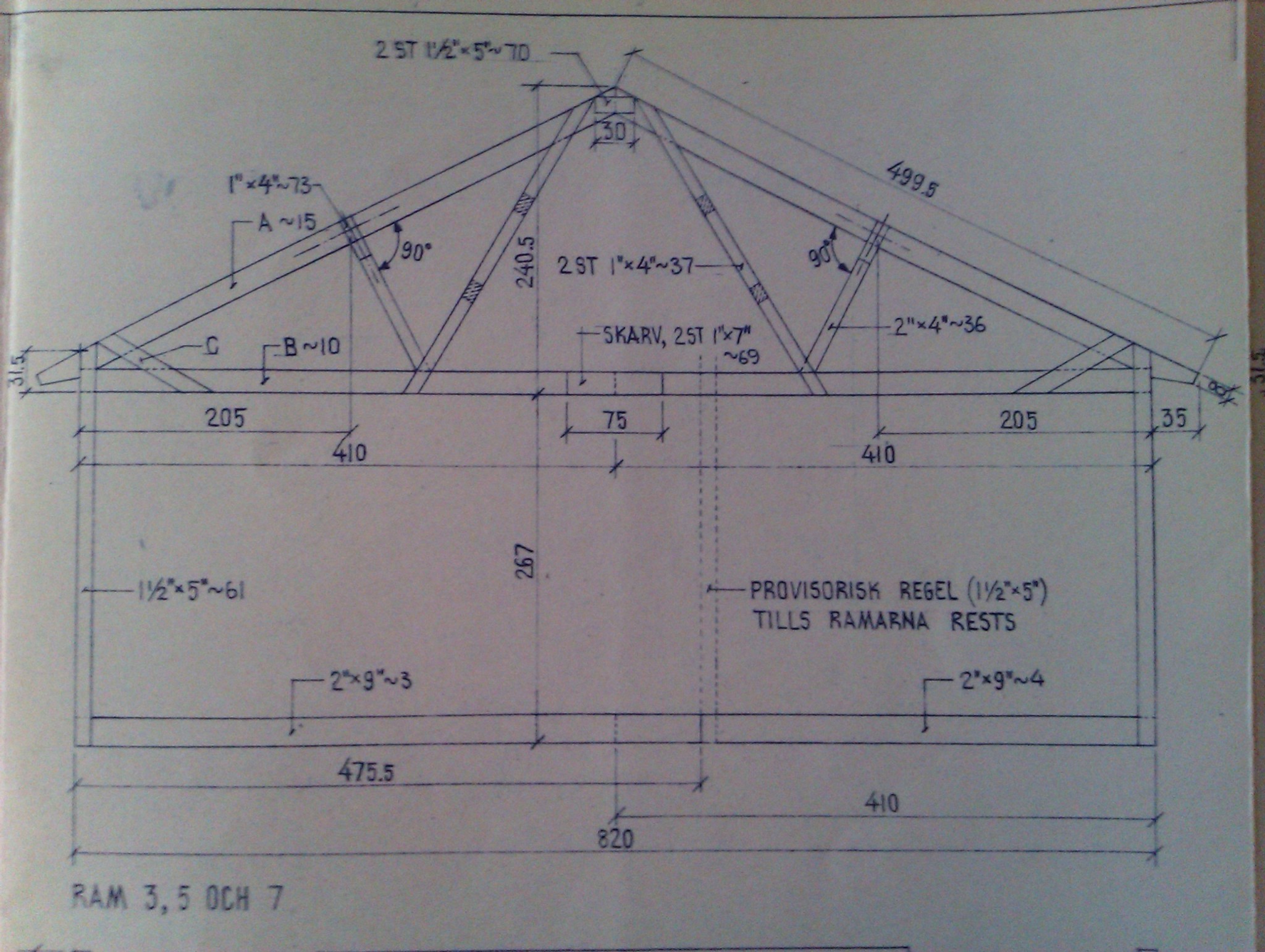
Look at the first image. This type of truss is found at lines 3, 5, and 7, and here there is no load-bearing wall, only closets. It is symmetrical and thus self-supporting.
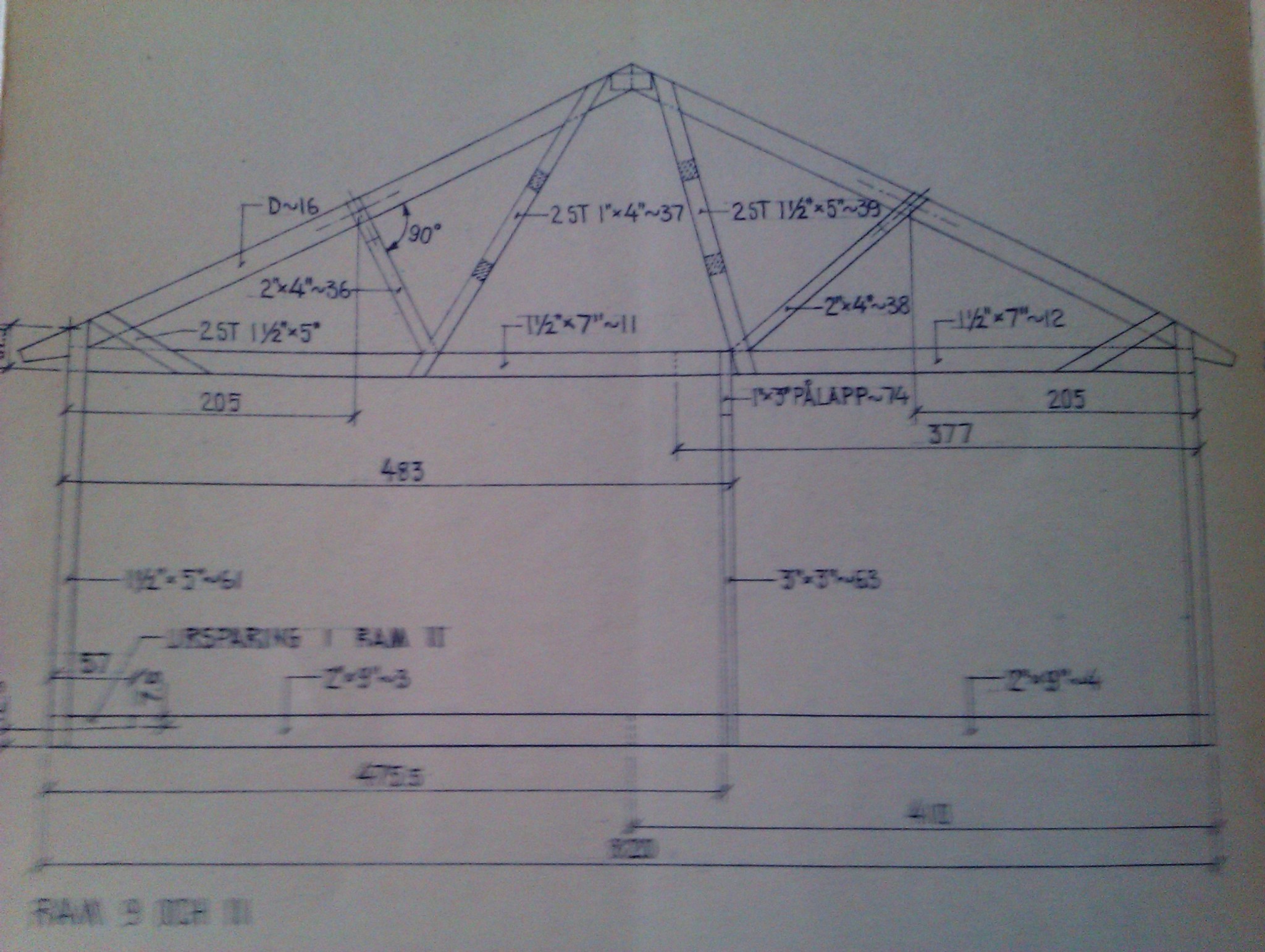
Second image: Here, the struts are slightly offset on the right side to meet a post in the load-bearing wall. This type is found at lines 9 and 11. Now there is no load-bearing wall here because the previous owner removed it and shifted up in the attic according to previous posts.
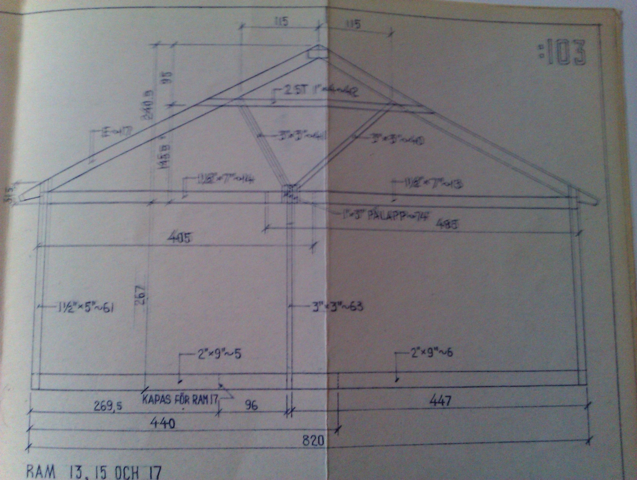
Image no. 3: Here there are only two angle struts that meet a post, 3"x3" in the other load-bearing wall that I want to remove. This truss is found in lines 13, 15, and 17.
Now comes the best part: In the attic, there is only one type of truss, and it is the model that stands in lines 3, 5, and 7. That is the self-supporting model. Why this is the case, only the builder might know, and he is probably long dead and buried.
What do you think, could this be correct? In the images above, one can see that there is no wall here, only closets.